How the Solar Tracking Works
During the day, the motor at the heart of it all gets its power from the motor-driver solar panel (MDSP). When it’s not shaded by the main panels, the MDSP causes the whole solar panel mount to lift and twist. As it does so, the MDSP becomes shaded by the main panels and, without power, the lift & twist stops.
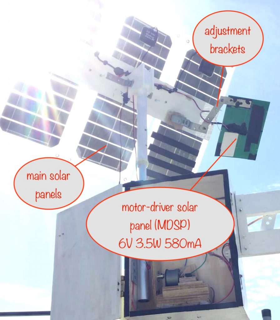
When the sun has moved across the sky enough so that the MDSP isn’t in shade any more, the motor once again fires up and does some more lifting and twisting.
The motor
The motor is a cheap 30rpm N20 available via ebay, Amazon, AliExpress – all the usual places.
To gear it down and increase the torque / lifting power, the motor is attached to a 90:1 gearbox (from AliExpress). This brings the rotation speed down to 1 revolution every 3 minutes – perfect for this project.
The N20 motor has a torque of 0.45kgf.cm meaning it can hold a 0.45kg weight at a distance of 1cm away from the motor shaft. With the 90:1 gearbox, the torque becomes 40.5kgf.cm (ignoring friction).
As the cord is tied to the nylon washer at a distance of 4cm from the motor shaft, the whole thing can lift around 10kg.
How the lifting and dropping is done
To keep things simple:
- the motor rotates in one direction only
- during the first half revolution the inner tube is lifted to the top of its travel
- during the second half revolution the inner tube is allowed to drop to the bottom of its travel
The nylon washer failed so I replaced it. The replacement failed as well. In both cases it got ripped under the lifting force. I’ve replaced it with a metal washer, smoothed with wet-and-dry so it doesn’t fray the cord. I also applied some more lubricant to the cord and around the slot – I used vaseline as it was to hand.
The cord got frayed by the slot at the top of the tube and snapped after a couple of months. I’ve now used a slightly different approach – an eye plate.
The lifting happens because the plate attached to the motor pulls on a cord which goes over and through a slot at the top of the outer aluminium tube through the eye of an eye plate and down between the two tubes. Finally, it’s attached to the bottom of the inner aluminium tube using a notch and knot.
If you know how engines work, the overall effect is like the way a crankshaft allows a piston to go up and down
See the next section for the cunning way that the vertical motion of the inner tube gets converted to a twisting motion so that the attached solar panels can follow the sun and then get reset to their dawn starting position.
How the twisting is done
It lifts, it twists, it drops, it reverse twists. Sounds like a type of dad-dancing!
The key to it is a helical slot in the outer tube and a guide pin fitted into that slot, and which is screwed firmly into the inner tube. The helical slot is just under 5cm in height (approx 2″).
As the inner tube is lifted or dropped, the guide pin forces the inner tube to rotate because it’s constrained to follow the helical slot.
When the solar panels have reached the top of their travel, they’ll have followed the sun all the way to point at the setting sun.
The helical slot has to go round by the same number of degrees as the difference between the degrees of the rising and setting sun. In the UK, at the height of summer, this is around 260°. To find out what it is for where you live, visit this page on TimeAndDate.com and search for your location.
Returning the solar panels to their dawn starting position
At dusk, there’ll be no power generated by the motor-driver solar panel but the motor still has to be driven to return the solar panels to their dawn starting position.
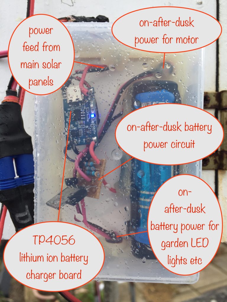
This power comes from a battery that’s kept charged during the day by the main solar panels and is switched on by an on-after-dusk circuit.
It doesn’t matter how far the solar panels have tracked the sun by the time dusk arrives, the end result is the same: the motor drives the plate around until they are pointing to the dawn starting position.
Circuit schematic
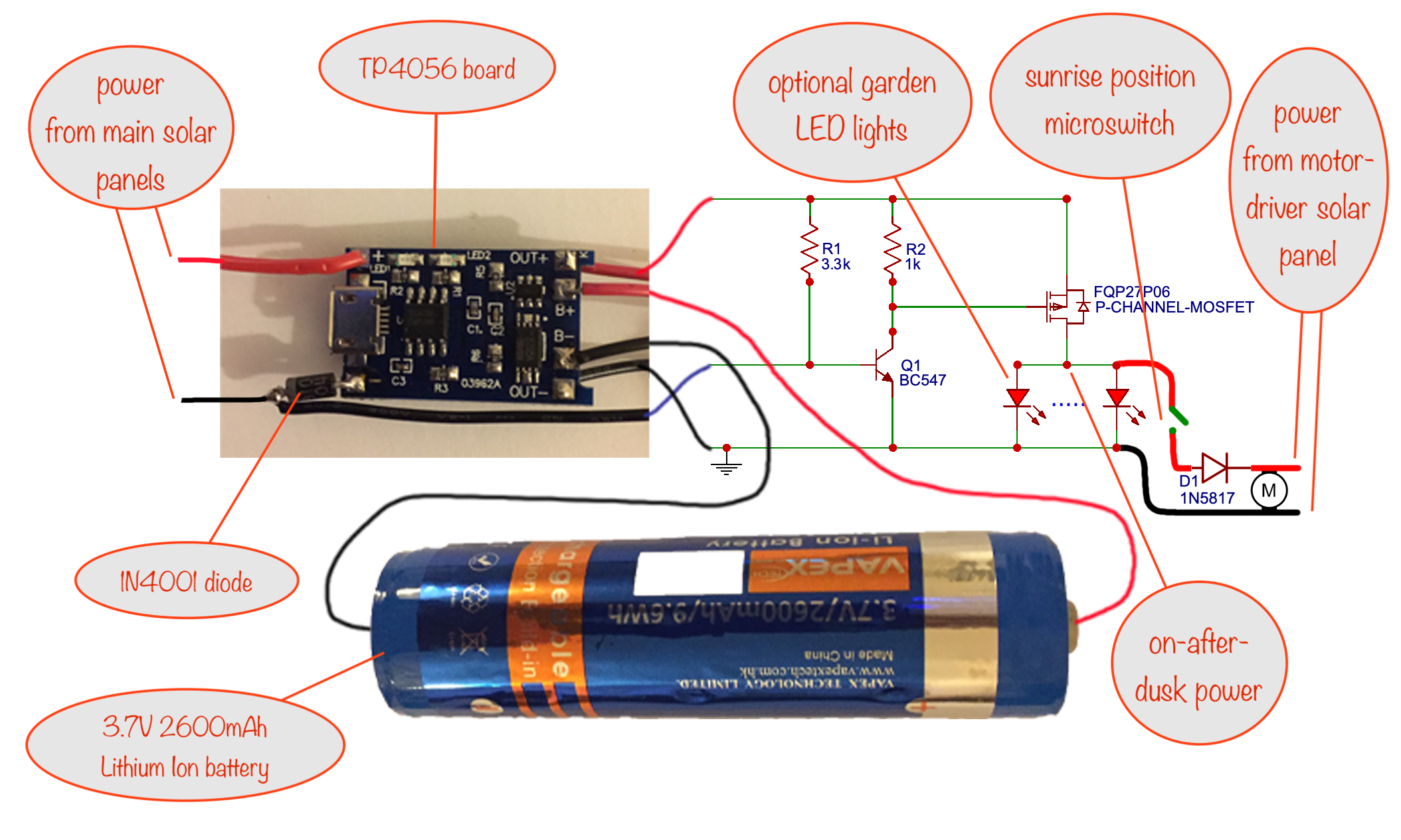
(click for a larger image in a new tab / window)
Note that the motor-driver solar panel has an inbuilt diode and it prevents the on-after-dusk battery power bypassing the motor through it.
A neat little circuit – based on the TP4056 charging board (with protection) for the battery – detects dusk because that’s when there’s no power being generated by the main solar panels. When it does, it provides battery power to the motor, causing it to continue rotating the plate.
credit: Samual Rebosura / Edmund Brisenio: YouTube video of Solar panel Lithium Ion battery charger.
Stopping the motor when the dawn start position is reached
As mentioned above, when the on-after-dusk circuit activates, battery power gets supplied to the motor and the plate starts rotating. All that’s left to do is to stop it when the solar panels have reached their dawn starting position.
This also happens to be when the inner aluminium tube has reached the bottom of its travel. This makes it easy to set up a fixed microswitch and a screwhead on the plate as its actuator. Lining it all up so it actuates at the right point is quite straightforward.
For the ultra observant, nothing happens if it’s been so overcast that the solar panels are still at their dawn starting position when dusk arrives. This is because the microswitch is still activated, preventing battery power reaching the motor.
When the sun comes up the next day, power comes once more from the motor driver solar panel and the lifting and twisting starts all over again.
Blowing in the wind…
One final thing I did to minimize any wobble when the wind blows is to put an end cap on the inner tube, after fixing the cord to the bottom.
All I did was take a plastic tube the same size as the inner diameter of the aluminium tube and press it firmly down onto a hot hob so that, as the plastic melted it splayed out. When it had cooled, I trimmed it to the same size as the inner diameter of the outer tube.
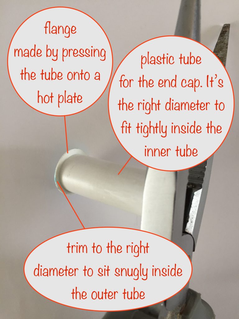
The result is that the end cap stops the inner tube from flopping around inside the outer tube when the wind blows.
Because this was added as an afterthought, luckily for me the inner tube at the bottom of its travel didn’t poke out the bottom of the outer tube. Also, the notch into which the cord slotted (with a knot preventing it from being pulled out) was deep enough that the end cap happily fitted into the end without interfering with the cord.
Unfortunately I forgot to take photos of it in place so, hopefully, the description is good enough to get across what I did.
Charging your batteries
Well, that’s the whole purpose of those solar panels, so now the solar tracking has been described, on with the battery charging aspects.
Only one of the main solar panels has to be 6V and that’s so the 3.7V lithium ion battery for returning the solar panels to their dawn starting position can be charged.
In my final version, I’ve gone for three 6 volt 10 watt solar panels connected in parallel and I use them exclusively for charging 3.7V lithium ion batteries. I use the well-known TP4056 modules to control the charging (just like in this project for charging the battery that drives the motor after dusk). Here’s the build project for them.
I could instead have mounted a variety of solar panels for different types / voltages of battery. For example:
- the 6 AA NiMH battery charging module needs a 12V 3½W solar panel
- the 2 AAA or 2 AA NiMH battery charging modules can both use 6V solar panels
So it all depends on the number and types of batteries you intend to charge as to what solar panels you mount.
When you get the needed 6V solar panel, get one that comes with a usb connector and that way you can add into the mix the ability to charge pretty much any device that can be charged with a usb cable.
Enjoy doing your bit to save the planet and prevent lots of CO2 going into the atmosphere!
Thanks for following along, comments welcome – you know what to do 🙂