Sun tracker prototype – another new motor

The previous motor was drawing too much current to be practical for the hobby solar panel I intend to use as the driver for it on the project.

new motor – 1.2 rpm at 6V – 120mA for 850g load

After a little hunting on the web, I found a likely candidate from the same manufacturer. A quick email confirmed that the motor was likely to do the job so I placed an order and waited a couple of days.

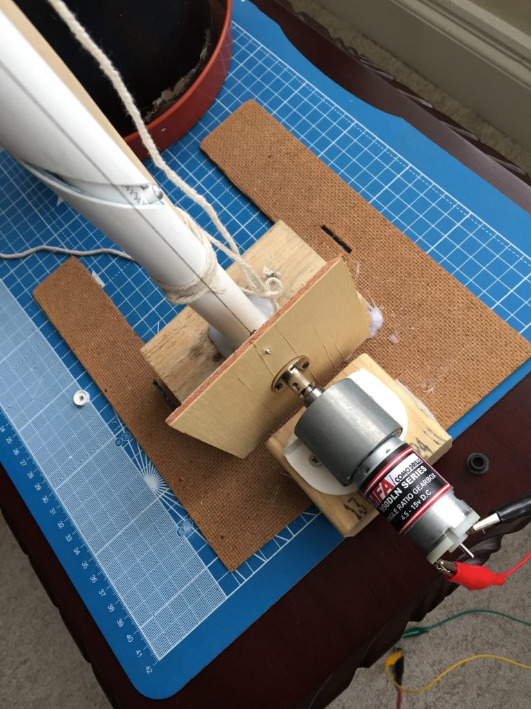
I’d also ordered a hub for connecting it to the rotating plate and it arrived on the same day. So after a quick swap and using some fishing line instead of thread I was ready for a test.

Perfect 😎

The plastic tubing I’m currently using in my prototype is too bendy, so I’ve swung the pendulum the other way and ordered some aluminium tubing.

I know it’s overkill for the combined weight of the solar panel, the driver solar panel, the circuitry and the enclosure but it’ll do for now.

A good friend is putting the helical slot into the outer aluminium tube because I don’t have the tools for it. He’s also promised a fancy 3D printed roller for the top of the tube to lift the fishing line away from the tube’s edge and so prevent it fraying.

I’ve ordered some clear acrylic and some rigid pvc tube today so I can see how they work out. Hopefully they’re rigid enough so they don’t flex but soft enough to make it easy for hobbyists to work with.

How it works

Principle

In the video you’ll see I’ve tied an old paintbrush to the outer tube to stop it bending.

The fishing line goes up from the rotating plate, over the top of the outer tube and is fixed to a slot in the bottom of the inner tube.

As the plate rotates (it always rotates in the same direction), it pulls on the fishing line, which then lifts the inner tube.

As it lifts, it’s forced to rotate by its pin being constrained in the helical slot cut in the outer tube. The helical slot forces it to rotate clockwise by approx 180° for the first half a revolution of the motor, counter clockwise for the second half.

Here’s the video:

new 1.2rpm motor in action, full rotation shown

In practice

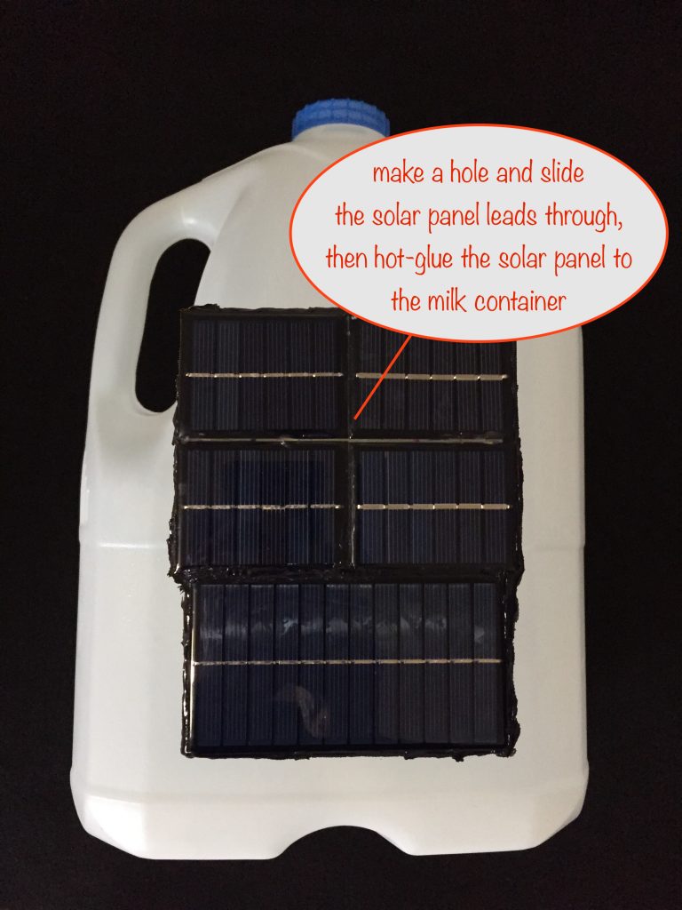
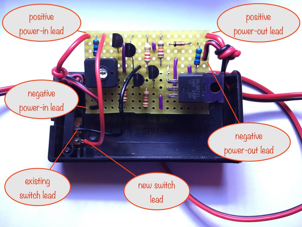
In practice, the milk container will be replaced by:

  • a mounted solar panel
  • the battery and charging circuit
  • a smaller driver solar panel for the motor

Start of day

  1. The main solar panel is facing in the direction of sunrise
  2. The driver solar panel will be shaded by the main one when the sun rises
  3. When the sun moves across the sky some, the driver solar panel is less and less shaded until it gets enough light to power the motor
  4. The motor turns the plate, lifting the inner tube and rotating the main solar panel until the driver solar panel gets more and more shaded by the main one
  5. When it’s shaded enough, the motor switches off and the main solar panel is now pointing directly in the sun’s direction.

Not enough sun?

If there’s not enough sun to power the driver motor, the main panel remains pointing wherever it happens to be.

That’s ok because on a cloudy day, it doesn’t really matter as the main solar panel will get roughly the same amount of light whichever direction it points in.

End of day

  1. When dusk falls, there’s no longer any power from the main solar panel and so the circuit isn’t charging the battery any more
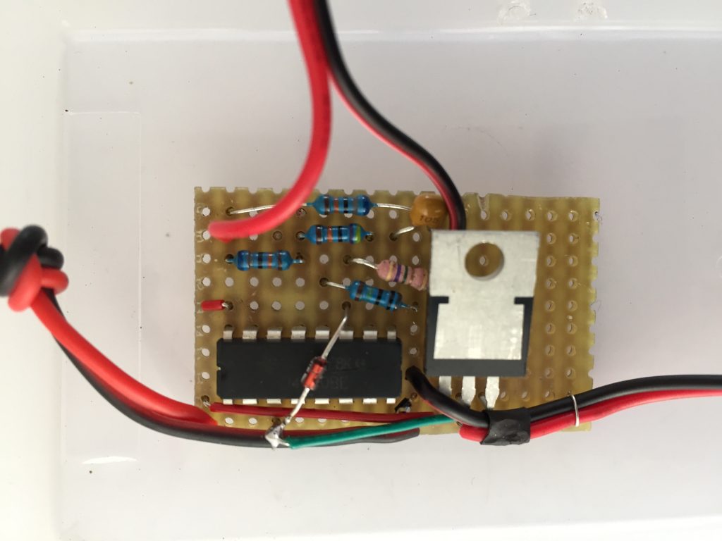
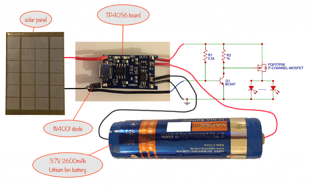
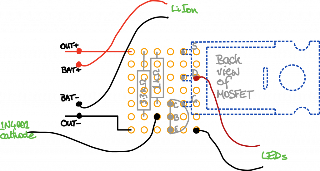
  2. When that happens, the Solar Lithium Ion Battery Charger module circuit as designed will start powering its connected load (an LED String module for example) and at the same time will supply power to the driver motor
  3. The motor will start turning (no matter in which direction the main solar panel is facing) until the helical slot returns the inner tube to the bottom of its travel
  4. As the motor turns, it’ll raise it first, if it wasn’t already at the top
  5. As it reaches the bottom:
    • the main solar panel is now pointing back in the direction where the sun will rise
    • the magnet at the bottom of the inner tube has now reached and lines up with the normally closed reed switch at the bottom of the outer tube
    • the reed switch opens, switching off the motor
    • NB a diode is used in series between the battery output power and the motor to prevent current back-flow through the driver solar panel

I’ll write another blog post when I’ve got the prototype to the next stage. Come back soon!

Solar tracker project – motor arrived

The motor I ordered has arrived and I’ve incorporated it into the prototype. Here’s how it now looks. Very Heath-Robinson! 🤪

motor operating the lift-and-twist mechanism

There’s still a few problems to solve. Mainly that the motor draws too much current for common and cheap hobby 6V solar panels.

After making the video I poured some water into the milk container to see what it did to the current drawn by the motor. It drew 250mA for only a combined weight to lift of around 500g. Without the water it’s about 100g, needing around 200mA.

Don’t quote me on those figures, they’re very rough and ready.

I’ve emailed the supplier of the motor for options, mentioning the following:

  • The solar panel I have to use can’t deliver the required load current unless it’s really bright sunshine. Besides, at 6V the 12 rpm is too fast.
  • I think a worm drive would work if I could get the final output shaft to rotate at 1rpm or less. Or maybe a pinion and timing belt???
  • Ideally I’d like something that would draw only 100ma under load so maybe an alternative motor would be better (with a worm drive / pinion-timing belt as well)???

Let’s see what they say.

That’s all until the next update 😎

Proof of Concept Solar Panel Sun Tracker

There are all sorts of commercially available sun trackers for solar panels but they are use sophisticated engineering / electronics.

Until now, there’s been nothing out there for the hobbyist. Have a look at this proof of concept video:

proof of concept Solar Panel Sun Tracker video

Details on driving the motor

Thanks to my good friend Bart, NightHawkInLight and NASA for one part of the solution…

The above video shows how to power the motor during the day for tracking the sun.

However, when the day draws to a close and the main solar panel is receiving no light, there’s still one thing left to do…

Resetting things ready for the following day

We have to drive the motor to rotate the plate another 180° to allow the inner tube to return to the starting position, resetting the solar panel so it points in the direction it was in at the start of the day.

That part is easy with the aid of a diode, reed switch and a magnet.

The Solar Lithium Ion Battery Charger module already has the capability to deliver power (from the battery) when darkness falls, so we use this power to drive the motor some more.

To stop the motor at the right time is where the diode, reed switch and magnet come into play:

sketch showing how the magnet and reed switch work in conjunction with the motor to return the inner tube to the bottom when dusk falls

When dusk falls, dark-activated power from the battery comes on. This drives the motor via the closed reed switch and the diode.

When the inner tube has returned to the bottom, the magnet activates the reed switch, opening it and cutting power to the motor. This leaves the inner tube at the bottom, with the main solar panel pointing in the direction it started at the beginning of the day.

When daylight arrives again, the secondary solar panels will once more start driving the motor as dictated by the sun’s position. The diode is there to protect the battery from any reverse voltage spikes generated by the motor.

I haven’t checked the exact operation of the secondary solar panels and motor yet, so another reed switch may be needed to prevent the dark activated power from leaking through them when the inner tube is being lowered by the motor.


That’s it for now. I’d love to hear your comments – especially if you spot any flaws!

Timer-delay Off Switch prototype

Written by team member, Mark Ridley

Timer-delay Off Switch prototype

I’ve been working on and have now completed the prototype for the Timer-delay Off Switch.

It’s purpose is to conserve battery juice – especially handy as it gets later in the year and there’s not enough sunlight to fully charge the battery each day.

It’s being tested outside right now with my Solar Lithium Ion Battery Charger that’s powering two 5-LED strings.

I’m just waiting for another 1/2 hour-ish for it to switch the LED strings off.

Here’s a photo of an earlier incarnation while I was adjusting the timing. Either I can’t do sums or I’ve misunderstood how to work them out. Either way, check out my resistor Christmas tree!

resistor Christmas tree while adjusting the delay-to-off timings

It was made more difficult because I need to allow a switch to change the timing between a 5 hour interval and an 8 hour one.

I’ve got my prototype switched to 5 hours and the LED strings switched on at 18:35. It’s just coming up to 23:30, so I keep peering round the curtains to see if they’ve switched off yet.

23:31 Not yet…

23:35 Not yet…

While I’m waiting… reed switches are fragile! I used one in the housing I’m using, hot glued it on top of a steel washer so that the magnet to actuate it placed on the outside of the housing would have something to cling to.

A washer, as I found, is no good. The hole means you get poles on the inside of the hole and around the circumference. That means the reed switch wouldn’t work properly when the magnet was brought close.

(23:41 Not yet…)

So I tried to remove the hot glue and hardly touched the reed switch – alas, the glass casing of the reed switch broke. Boo hoo!

So when the replacement arrives, I’ll be using a small steel plate this time and not a washer.

23:45 Not yet… I guess this calls for a cup of tea 😉

As a side note, I notice that as the colours on the LED strings change, when it comes to blue, they’re very dim. From past experience I know this means that the battery voltage must be getting quite low – so the timer-delay off switch is really needed at this time of year when using a 1.5 Watt solar panel.

23:55 Not yet…

00:22 Yaay! They’ve switched off.

So that’s around 5 3/4 hours. How consistent is this? I’ll time it again tomorrow and update this post with the result.

Update: It’s now tomorrow and it took 5 1/2 hours to switch off this time.

See the now-completed project build tutorial for it here

Electronics projects for Kids 12+ and Adults

We’ve recently been working on a number of practical, related projects you can build giving you useful electronics light emitting diode (LED) gadgets.

Here’s a few photos taken from the projects that have been completed, just to give you an idea of what to expect:

Apart from the Memory Flash Reminder, which is a standalone project, the rest are all mix ‘n match modules. This one in particular is a great gift for grandparents – and there’s plenty of time to make it as a Christmas present 🙂

The mix ‘ match ones are all designed so you can build the ones you like and then hook them up in different ways to suit you.

And when you’ve made them, they make great gifts that people will love receiving (especially the fibre optics!)

There are still more in the works (LED strings and Timer-delay Off Switch coming next, night-time porch light coming later).