June 2 2022: Updated to correct typo. R2 was 3.3kΩ and should have been around 1kΩ (3.3kΩ is way too high for the green LED to come on.)
this solar panel powered battery charger for 6 rechargeable AA NiMH is another module in the Nifty Hobby Projects for LEDs and Solar series
Written by team-member Mark Ridley
This tutorial shows you how to build a charger for 6 AA NiMH batteries. You decide on which two battery capacities you want to be able to charge with it and there’s a switch to let you flip between them.
- to build one for 2 AAA batteries, see this project
- to charge 2 AA batteries at a time, see this project
- to use it to charge a battery pack consisting of 2 stacks, each of 3 AA batteries, build this project
Set up your circuit for the 2 lowest capacity batteries you have and they’ll take one sunny day (10 hours) to charge. Then any higher capacity batteries can still be charged without harm – they’ll just take longer.
For example, I’ve set mine up to charge 1000mAh or 2000mAh batteries. I’ve got some 2900mAh batteries as well and they’ll happily charge in around a day and a half on the 2000mAh setting.
Description
If you want to charge AA NiMH batteries, then this project lets you charge six at a time. You decide on which two battery capacities you want to be able to charge with it and there’s a switch to let you flip between them.
Using renewable energy is really important as we try and counter the effects of global warming and this a fantastic and practical project for a small step in that direction – and every household needs one!
If your kids (or you are one) have already shown interest in saving the planet by fighting climate change, this could be a great project for them to get involved with. Who knows where it might lead?
On a more practical note, using a solar panel to recharge your NiMH AA batteries means you’ll always have some fully charged and ready to be used. Perfect for TV remotes, toys and other battery-operated goodies.
It’ll take one sunny day (10 hours) to get them fully charged and you can charge two at a time or six at a time depending on the options you choose.
Features of Module
Whichever way you want to go, you’ll find the options here to achieve what you want:
- charges 6 NiMH batteries
- switches between charging each of the two battery capacities that you choose
- green LED indicates when enough charging volts are present
- red LED indicates when batteries are fully charged (1.5V per battery so 9V for 6)
- manufacturers’ recommended C/10 charging used so leaving them on charge once they’re fully charged won’t cause them any harm
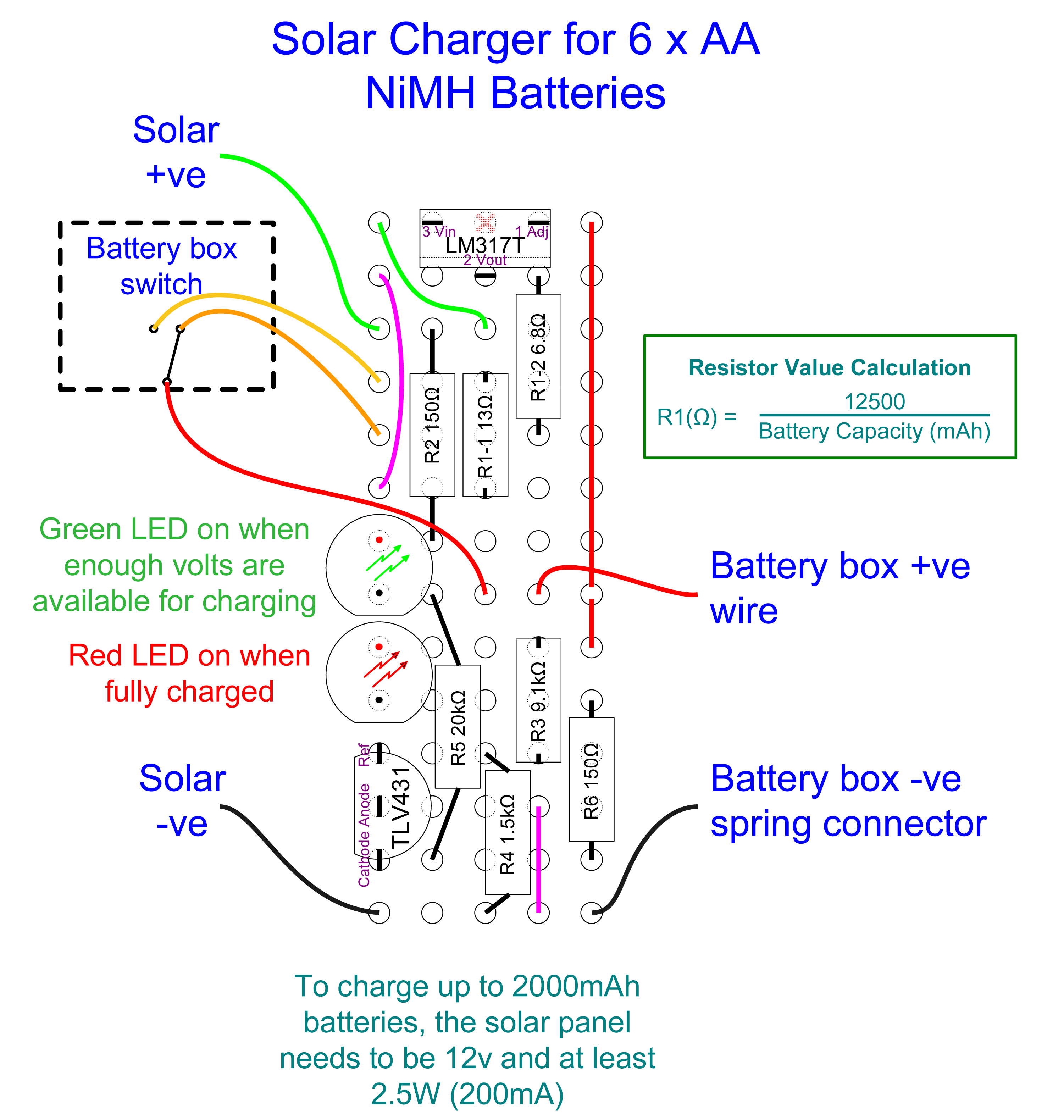
Circuit Diagram

(click to see larger in new tab)
The only things that need changing in the circuit diagram are the values for R1-1 and R1-2.
Their values depend on the two different capacities of battery you intend to charge and you can find the values to use for each of the common NiMH battery capacities in the table at the end.
Note that, despite the correct calculation of the values for the voltage divider resistors (R3 and R4), I had to put another 47Ω in series between ground and the 1.5kΩ resistor, R4. Perhaps some tolerances were off.
Without it, the red LED never came on, despite the batteries becoming fully charged.
Circuit notes
The circuit is split into two parts:
- a constant current section for charging the batteries
- a voltage monitor section for indicating when the batteries are charged
Contant current section
This gets its power from the attached solar panel when the sun is shining and uses an LM317T chip to convert its power to a constant current for charging the batteries.
When there’s enough power available from the solar panel to feed any charge into the batteries, the green LED will be on. If it’s very dim, then you’ll only be getting maybe 10 or 20 milliamps into your batteries but at normal brightness, all is good.
The way that the LM317 works is that (given enough input voltage on VI, pin 3) it will ensure the output voltage (VO, pin 2) is 1.25V higher than the voltage present on the Adjustment (pin 1). So the required constant current (take 100mA in the following as an example) is achieved with a resistor whose value is given by:
R = V/I ⇒ R = 1.25/0.1 ⇒ R = 12.5Ω
The two values of R1 used in the schematic, 13Ω and 6.8Ω, limit the current to just under 100mA and 200mA respectively. That’s the highest recommended charging current for 1000Ah and 2000mAh NiMH batteries (C/10).
Voltage monitor section
This section uses a TLV431 adjustable shunt regulator chip to turn on the red LED when the voltage set by the values for R3 and R4 is reached.
With the values given in the schematic, the LED will switch on when the voltage across the batteries reaches 8.8V.
A fully-charged 1.2V NiMH battery is 1.5V, so 6 in series will be 9V. This means that when the red LED comes on, they’ll be at maybe 98% or so of full charge.
Note that leaving them on charge when they’re fully charged won’t cause any damage because the current is limited to C/10 as recommended by battery manufacturers.
About the solar panel
The solar panel you’ll need for 6 batteries is 12V (9 volts for the batteries and 3 volts headroom for the LM317T). The power it has to deliver depends on the highest capacity batteries you’ll be charging. See the table at the end for details.
It’s ok to use a solar panel capable of delivering more power but don’t exceed the 12V or the LM317 will end up running hot.
NB If your solar panel includes a blocking diode, it’s not needed so you can short it out. That way the panel’s full voltage is delivered to the circuit, helping the headroom needed by the LM317T.
Components list:
- LM317T Adjustable Regulator for the constant current source (T means it’s a TO-220 package, designed for higher currents)
- TLV431 Shunt Regulator for the charge completion detection
- 1 x Green LED
- 1 x Red LED
- R1-1: Given here as 13Ω for a 1000mAh battery capacity
- R1-2: Given here as 6.8Ω for a 2000mAh battery capacity
- R2: 150Ω current limiter for green LED
- R3: 9.1kΩ
- R4: 1.5kΩ
- R5: 20kΩ
- R6: 150Ω current limiter for red LED
- hookup wire
- 1.6mm diameter heatshrink tubing
Tools etc. you’ll need:
- 18 Watt soldering iron, 25 Watts at a push
- “Helping Hand”
 – invaluable aid while soldering or gluing
 - Wire strippers covering 26 to 16 AWG
- Side cutters
- Small snipe-nose / needle-nose pliers
- Glue gun for fixing everything in place
- UV glue for letting LED light shine through the battery box
- Small hobbyist drill with a 2mm, 3mm and 4 or 5mm drill bit
Preparing the battery box
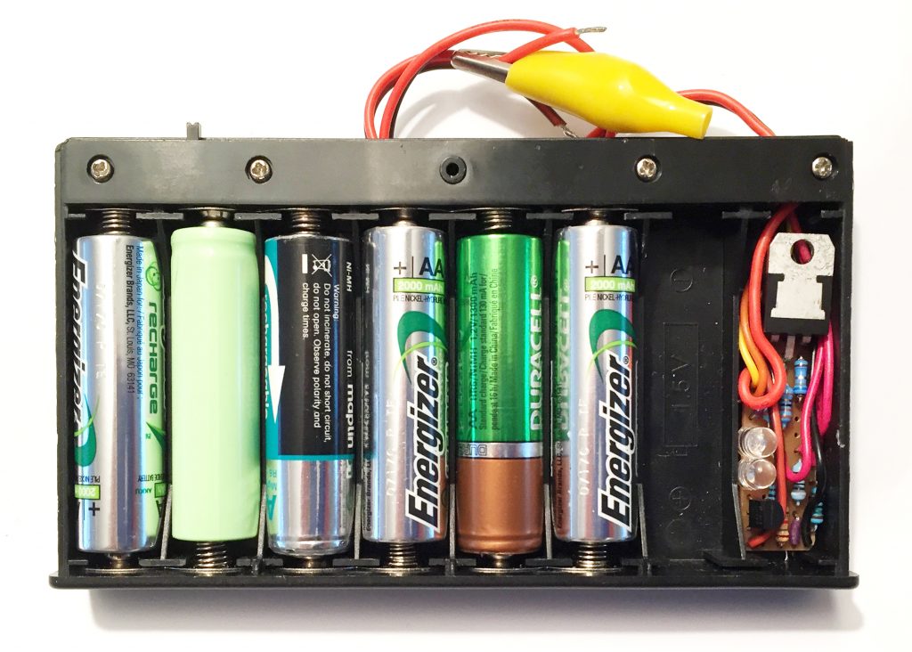
The circuit fits neatly into one slot in a standard 1.5V battery box so for this 6 battery setup you’ll need an 8-battery box (they don’t make one to hold just 7 batteries).
Why can’t you charge 7 batteries? It’s because the contant current part of the circuit needs around 3V headroom between the 12V Solar Panel and the fully charged battery voltage. With 7 batteries, that would be 10.5V leaving only 1.5V headroom.
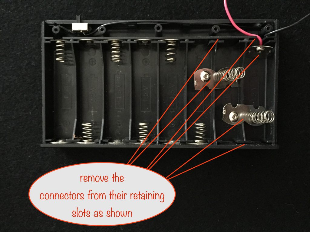
First, remove the cover at the top to expose the switch. Next you remove the two right-hand connectors from their retaining slots to free up the battery slots:
You’re going to move the positive connector into the 6th slot so, to make room for its wire, cut a slot for it in the plastic before you slide the connector into its new position.
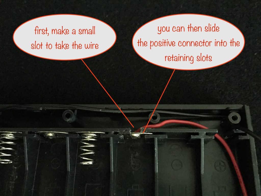
I used my sidecutters to make the slot, snipping off a small piece at a time.
We’ll leave the preparation of the switch until after you’ve built the circuit on the stripboard.
Building the circuit
Stripboard layout
Here’s the stripboard layout of the circuit. With the values shown for R1, you’ll be able to charge 1000mAh and 2000mAh batteries.
(click to see larger in new tab)
Decide on the two capacities of battery you want to be able to charge. Look in the table at the end to find the corresponding values for R1 and use them. It makes sense to use the left position of the switch, the one marked “off” on the battery box, for the lower capacity battery (highest value of R1) and vice versa.
Preparing the battery box switch
Now that you’ve got your circuit ready you can go ahead and get the switch and wires ready for hooking up to it.
You’ll be desoldering the existing wires on the switch and the left-most slot’s negative connector. The existing long black wire on the switch is to be moved to the spring connector:
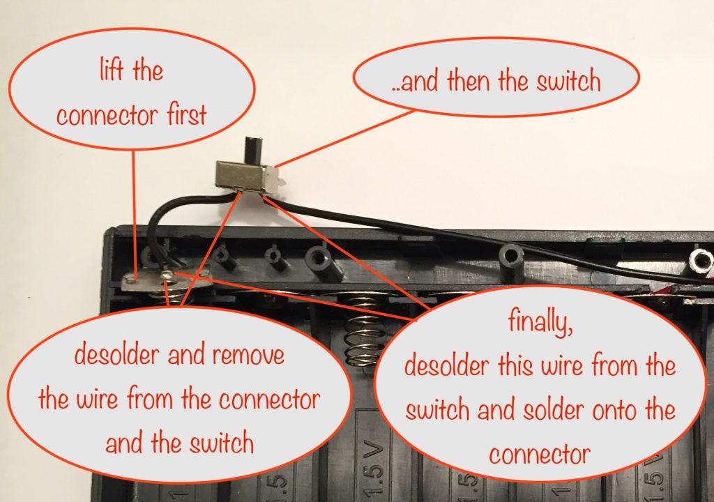
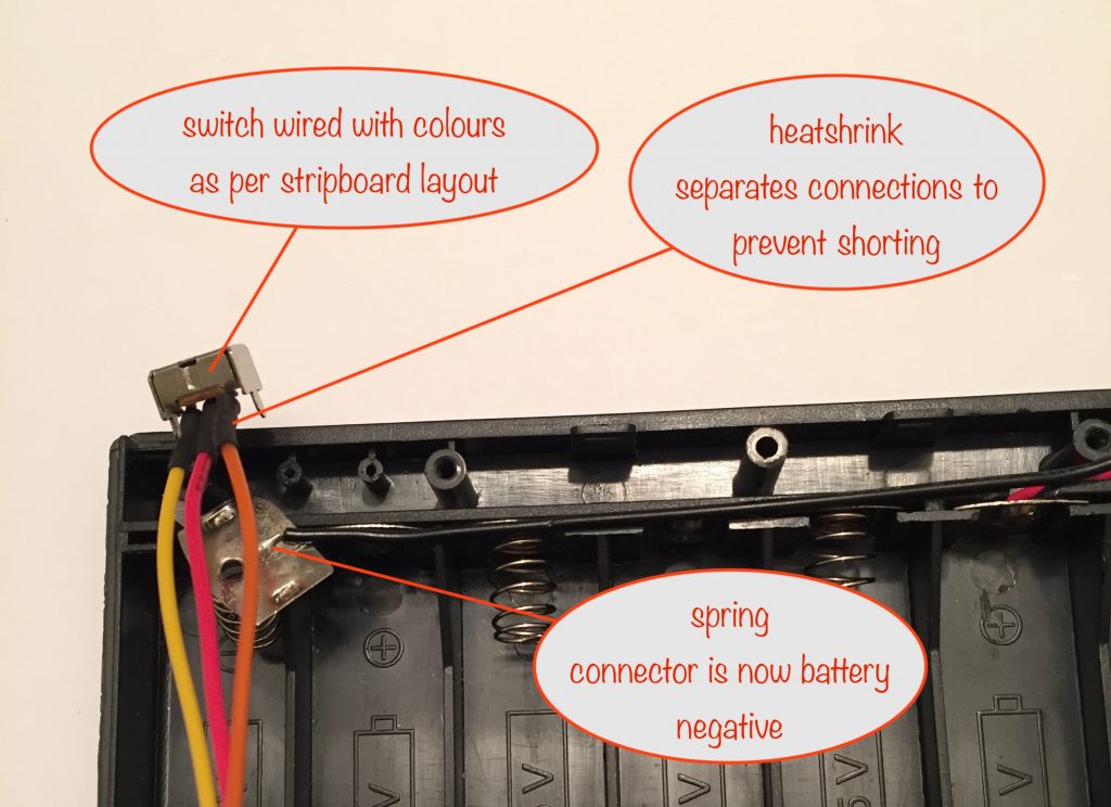
You’ll then connect some new hookup wires to all three of the switch’s terminals.
With:
- the three new wires
- the red positive wire
- the existing long black wire (now conencted to the battery negative spring connector)
….you’ll have everything you need to connect to the stripboard. Everything except the solar panel twin wires, which we’ll deal with shortly.
With those three hookup wires soldered to the switch, it’s a good idea to check that the switch correctly connects the centre wire (red) to the outer two wires (yellow and orange).
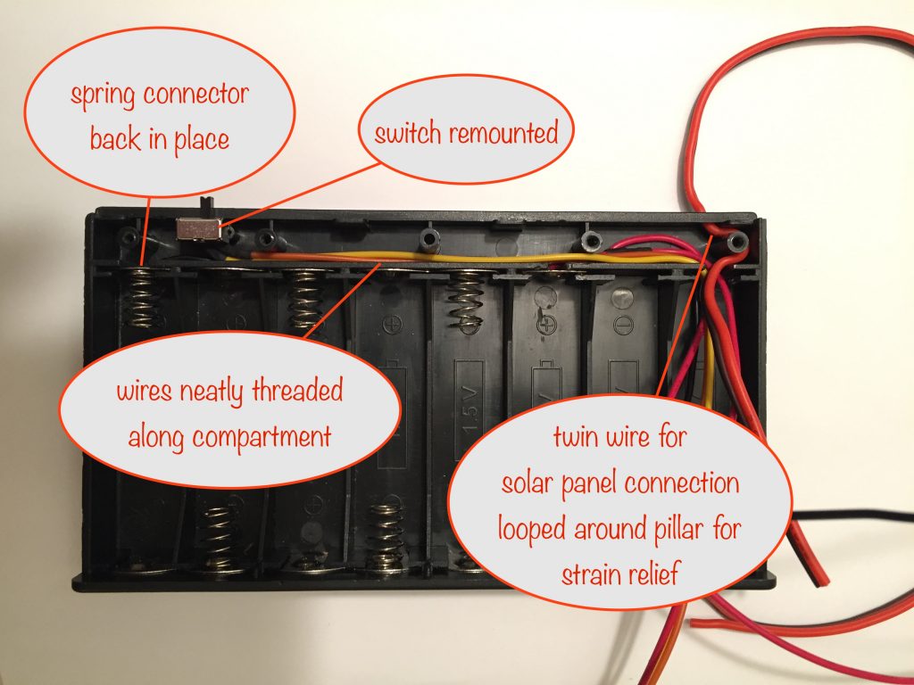
Assuming all is well, it’s now time to:
- place the spring connector back into its retaining slot
- lock the switch into position in its mounts
- thread the new wires along the compartment
- add the twin wire for the solar panel
Here’s what it looks like. Note that I’ve threaded the twin wires for the solar panel through the hole in the battery box and looped them around the pillar for strain relief:
Building the stripboard
Place all the components on the stripboard, following the layout diagram above, and solder them in place. Use your sidecutters to trim off the excess components leads.
Next, solder the wires you threaded along the switch compartment and add and solder the solar panel twin wires.
Once you’ve done that, you’re ready for testing it works as expected (see below).
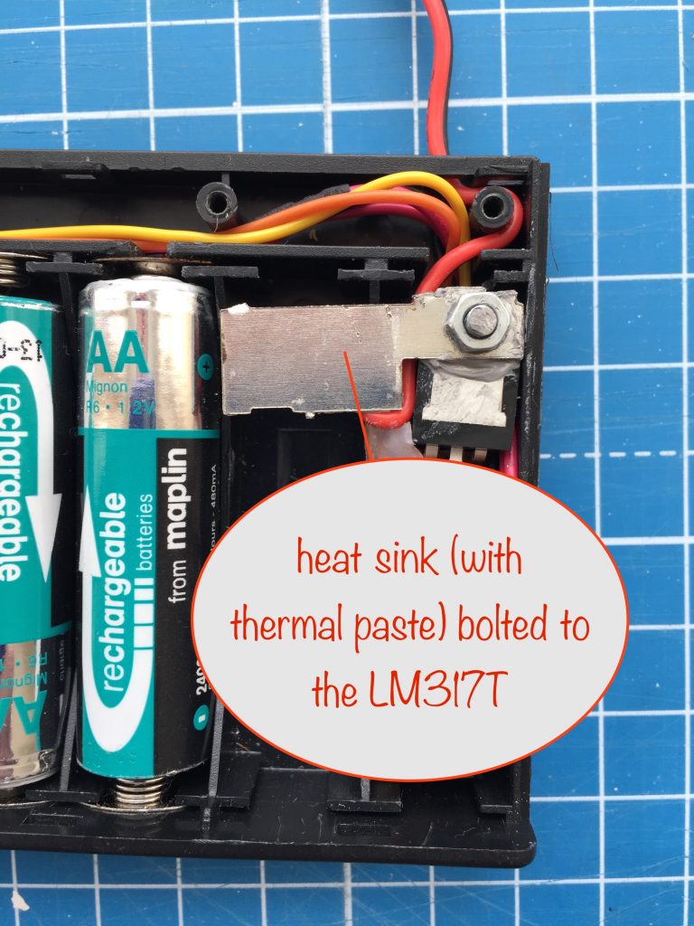
Heat sink
If you’re going to be charging 2000mAh batteries or above, you’ll need to use a heatsink on the LM317T. I used a piece of metal plate I had lying around. Cutting a piece from a cola can works just as well.
I’ve used thermal paste to ensure good heat transfer but if you don’t have any you can use a thin washer to make sure even contact and then use a larger piece of metal.
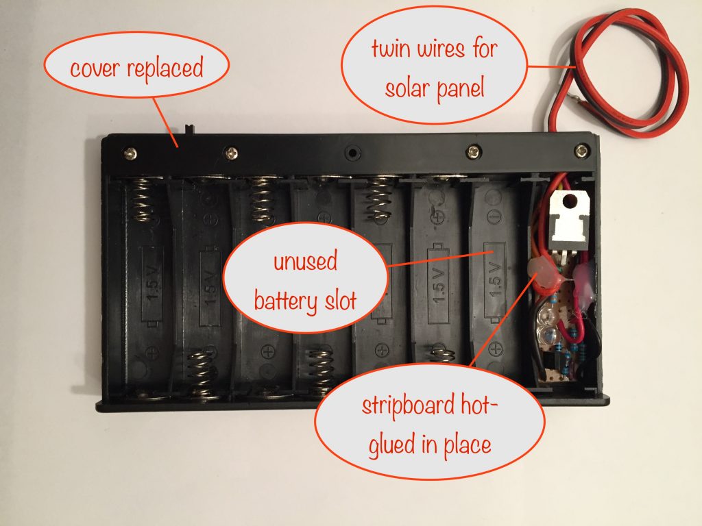
There’s plenty of room in the unused battery slot, so even if you’re charging batteries needing a charging current greater than 200mA, you’re good to go.
I’m charging at a maximum of just under 200mA (for 2000mAh batteries) and this is what my heatsink looks like:
Testing your battery charger
Put the solar panel where it’ll catch most light during the day. The battery box isn’t weatherproof so it’ll need to be indoors or otherwise protected in case it rains.
The green LED will light up when there’s enough volts being generated by the solar panel.
Put in the batteries you want to charge (all the same capacity) and make sure you’ve set the switch correctly for their capacity.
When the red LED lights up, the batteries are fully charged. If you start with batteries that are fully discharged it should take around 10 hours of full sunshine.
Note that you can charge higher capacities than your switch setting but it’ll take longer than 10 hours. Charging higher capacity batteries in this way is perfectly safe and they won’t come to any harm.
Finishing touches
Do this step while you’re testing as it gives you something to do 🙂
So the last thing to do is to allow the LEDs to shine through the battery box cover. You do this by drilling two 5mm holes so they align with the LEDs and then filling them with UV glue.
To stop the UV glue leaking out, put a piece of sticky tape on the underneath before you put a few drops of UV glue into the hole from the top. Set the glue with the supplied UV LED and then remove the sticky tape – and that’s you done.
Once you’re happy with your testing and you’re sure all is well, you’re ready to use hot-glue to hold everything in place.
I’d recommend using a 2.1mm dc power connector socket on the solar panel wires so you can easily connect and disconnect the solar panel. Many of them come with a 2.1mm plug and if yours doesn’t, it’s easy enough to solder one on.
And in conclusion
Thanks for following along and, even if you haven’t built the project, I’m sure you’ve learned a few things on the way.
I’d love to hear what you think, so please drop off a comment. If you did build it, let us all know how it went.
Thanks!
Battery capacities and resistor value(s) for C/10 charging
Decide on the two capacities of battery you want to be able to charge. Look in the table to find the corresponding values for R1 and use them. It makes sense to use the left position of the switch for the lower capacity battery (highest value of R1) and vice versa.
The minimum wattage of the solar panel you’ll need depends on the capacity of the batteries you’ll be charging. That’s because their capacity dictates the C/10 safe charging current so solar panel Watts = Volts x Amps. But never mind that, just get a 12 Volt 4 Watt solar panel and it will cover everything here and give you some spare capacity for days when it’s not quite so sunny.
Note that if you’re charging battery capacities under 2000mAh then 1/4 Watt for R1 will be fine.
If you’re charging battery capacities between 2000 and 2350mAh then R1 will need to be 1/3rd Watt.
With 2400 mAh batteries or above you’ll need 1/2 Watt for R1.
| Battery Capacity (mAh) | C/10 current (mA) | Nearest R1 value (Ω) | Charging current using R1 (mA) | 12v Solar Panel (Watts) |
| 500 | 50 | 27 | 46 | 0.7 |
| 550 | 55 | 24 | 52 | 0.8 |
| 600 | 60 | 22 | 57 | 1 |
| 650 | 65 | 20 | 63 | 1 |
| 700 | 70 | 18 | 69 | 1 |
| 750 | 75 | 18 | 69 | 1 |
| 800 | 80 | 16 | 78 | 1.5 |
| 900 | 90 | 15 | 83 | 1.5 |
| 930 | 93 | 15 | 83 | 1.5 |
| 950 | 95 | 15 | 83 | 1.5 |
| 1000 | 100 | 13 | 96 | 1.5 |
| 1100 | 110 | 12 | 104 | 1.5 |
| 1300 | 130 | 10 | 125 | 2.5 |
| 1900 | 190 | 6.8 | 183 | 2.5 |
| 2000 | 200 | 6.8 | 183 | 2.5 |
| 2100 | 210 | 6.2 | 202 | 3 |
| 2300 | 230 | 5.6 | 223 | 3 |
| 2350 | 235 | 5.6 | 223 | 3 |
| 2400 | 240 | 5.6 | 223 | 3 |
| 2500 | 250 | 5.1 | 245 | 3.5 |
| 2550 | 255 | 5.1 | 245 | 3.5 |
| 2600 | 260 | 5.1 | 245 | 3.5 |
| 2700 | 270 | 4.7 | 266 | 3.5 |
| 2800 | 280 | 4.7 | 266 | 3.5 |
| 2850 | 285 | 4.7 | 266 | 3.5 |
| 2900 | 290 | 4.7 | 266 | 3.5 |
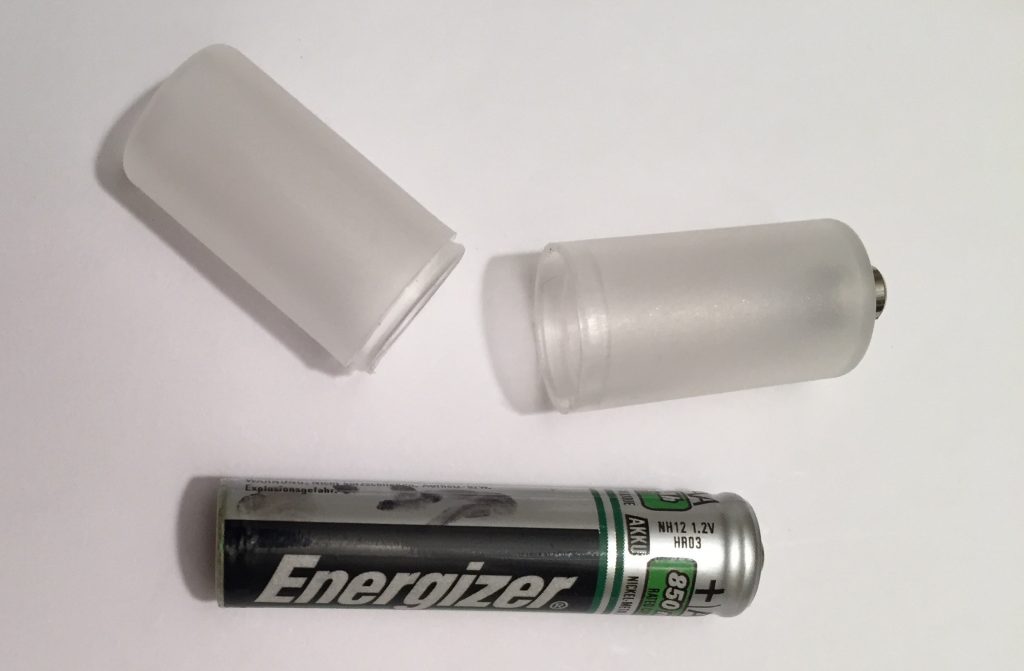
Personally, I’ve gone for 1 solar panel that I use to switch between charging 6 1000mAh AAA and 6 2000mAh AA batteries, depending on need. I’ve got some cheap tube-style adaptors that let me use AAA batteries in an AA battery box so I need only one circuit and one battery box.
I just need to take care that I set the switch correctly for the batteries I’m charging because their C/10 charging currents are different for the different capacities and I don’t want to damage them.
Other projects in the Nifty Hobby Projects for LEDs and Solar series (so far, more to come very soon):
- Flasher Memory Aid
- Dark-activated Switch
- 5 LED String
- Fibre Optic Display
- Mini Sparkles Colour-changing LED Fibre Optic String
- Solar Lithium Ion Battery Charger
- Solar NiMH Battery Charger for 2 AAA batteries
- Solar NiMH Battery Charger for 2 AA batteries
- Timer-delay Off Switch
- 4-LED Porch Light
- 10-LED Bedside lamp
- Mini Camping / Bedtime Reading Lamp
- Main page with links to where to buy stuff
Read all about NiMH rechargeable batteries on the Wikipedia Nickel-metal hydride battery page (opens in new tab / window)