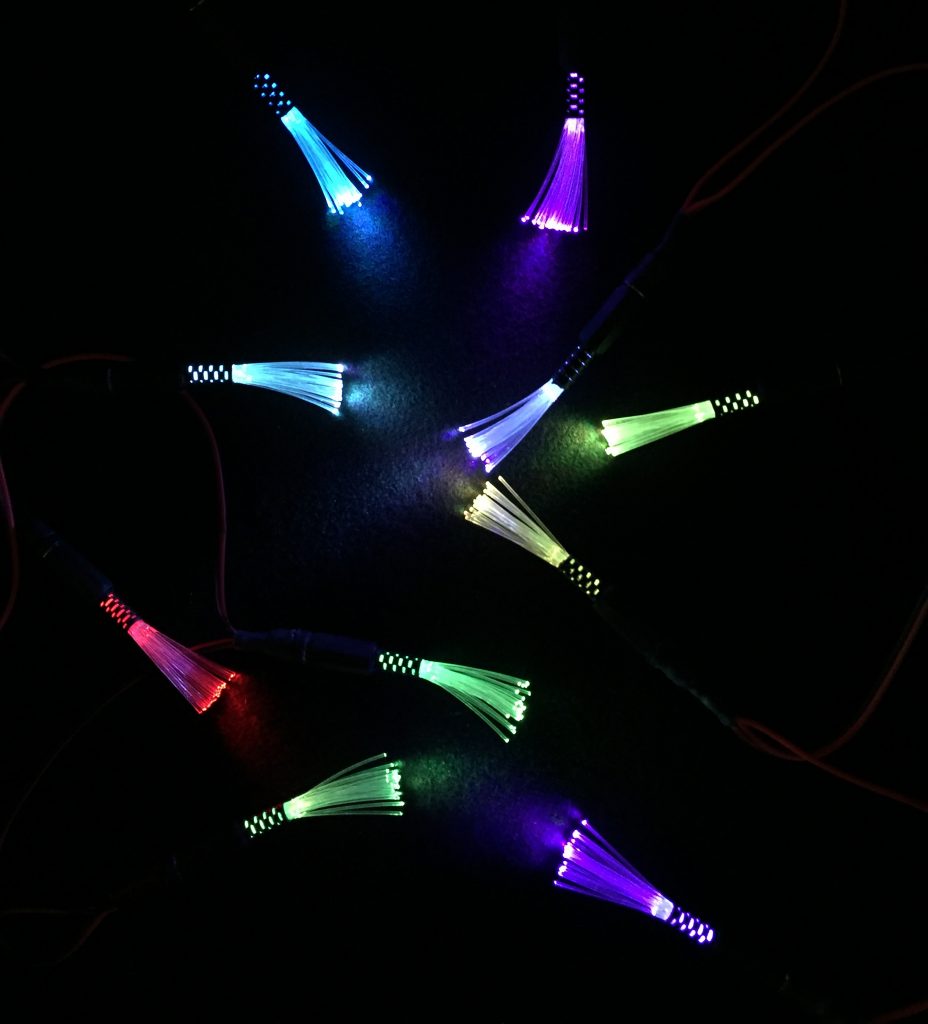
this is another mix ‘n match module in the Nifty Hobby Projects for LEDs and Solar series
Preparation
Tools etc. you’ll need:
- 18 Watt soldering iron, 25 Watts at a push
- Desoldering pump / solder wick – in case of mistakes!
- “Helping Hand”
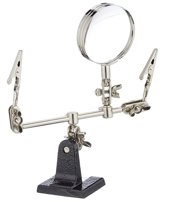 – invaluable aid while soldering
 - Wire strippers covering 26 to 16 AWG
- Side cutters
- Chunky electricians side-cutters (so you don’t ruin your good ones when cutting the metal of the DC plug connectors – see below)
- Small snipe-nose / needle-nose pliers
- 4.5mm drill bit as a former for 4.8mm heat shrink
Components / parts list
See the main page (opens in new tab) for links to where you can buy these.
- 10 x 5mm RGB slow colour-changing LEDs
- 15m x 0.75mm fibre optic cable cut into 5cm lengths (29 per mini sparkle – ok that’d be 14.5m but it’s good to have a little extra)
- 3.2mm diameter heat shrink tubing
- 4.8mm diameter heat shrink tubing
- 9mm diameter self-adhesive heat shrink tubing
- 10 Pairs 3.5 * 1.3mm DC Plug and Panel Mount Socket Connector
- 2.2m of 22awg 0.3mm² super-flexible 2-core silicone wire for the string, cut into 11 x 20cm lengths
- your choice of connector. As this is for indoor use, for power-in I’m using a 2.1mm DC power in-line socket and for power-out (to allow more than one string to be strung together) a matching 2.1mm DC power plug
- 10 Pairs 3.5 * 1.3mm DC Plug and Panel Mount Socket Connector
- 4.5mm drill bit as a former for the 4.8mm heat shrink to make a 4.5mm collar for the 29-fibre bundle
- A small length of old mains cable – around 5cm is fine – to source the short lengths of sheathing used to splay out the fibres in the mini sparkels
On with the build…
The build
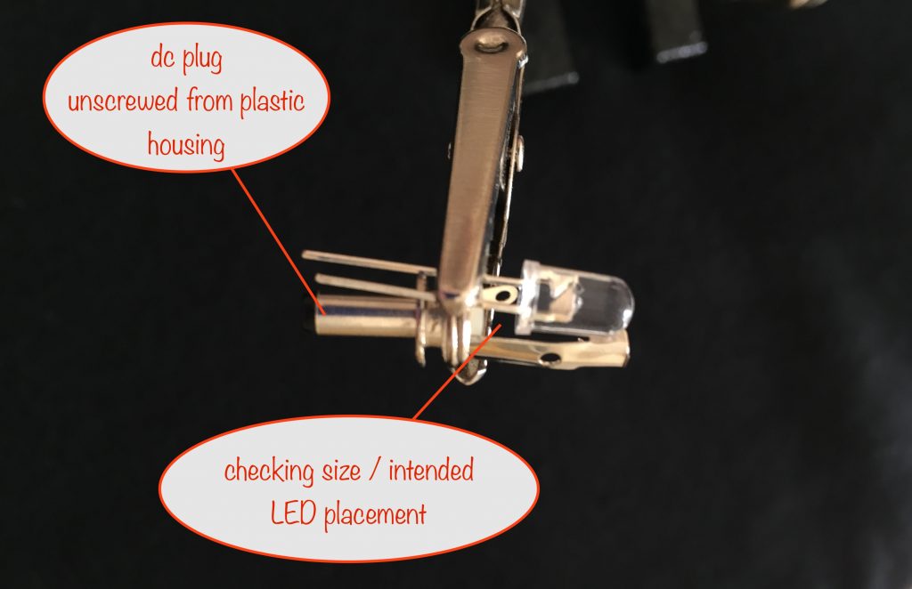
Mounting the LED in the 1.3mm DC Plug
Take one of the DC plugs and unscrew the plug part from the pastic housing. Take a moment to check the sizing / intended placement of the LED.
Use the chunky electricians side cutters (make sure you have cleared it with the owner first!) to cut the connectors as shown in the next photo.
You need to be careful with accuracy of cutting here as there’s so little room to spare for mounting the LED. The important thing is that it’ll all fit back together when the fibre bundle is in place.
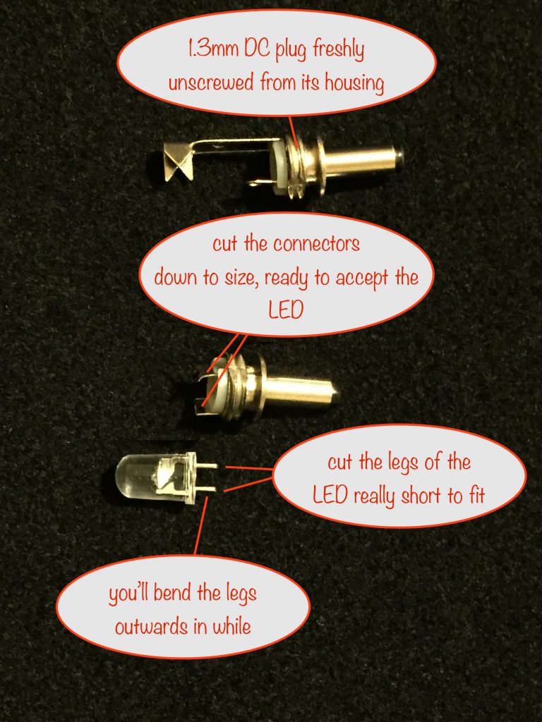
Straighten the connectors if needed and then bend the legs of the LED to touch them. This is so everything’s ready for you to start soldering.
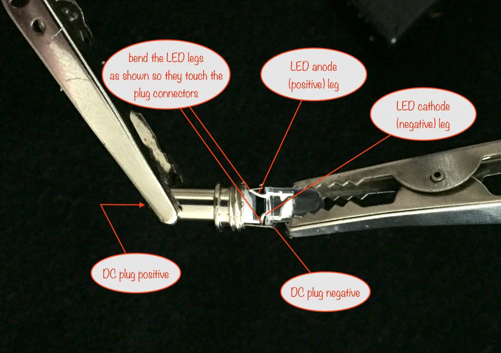
The next thing you’ll do is solder the negative (cathode) LED leg to the negative connector of the DC plug.
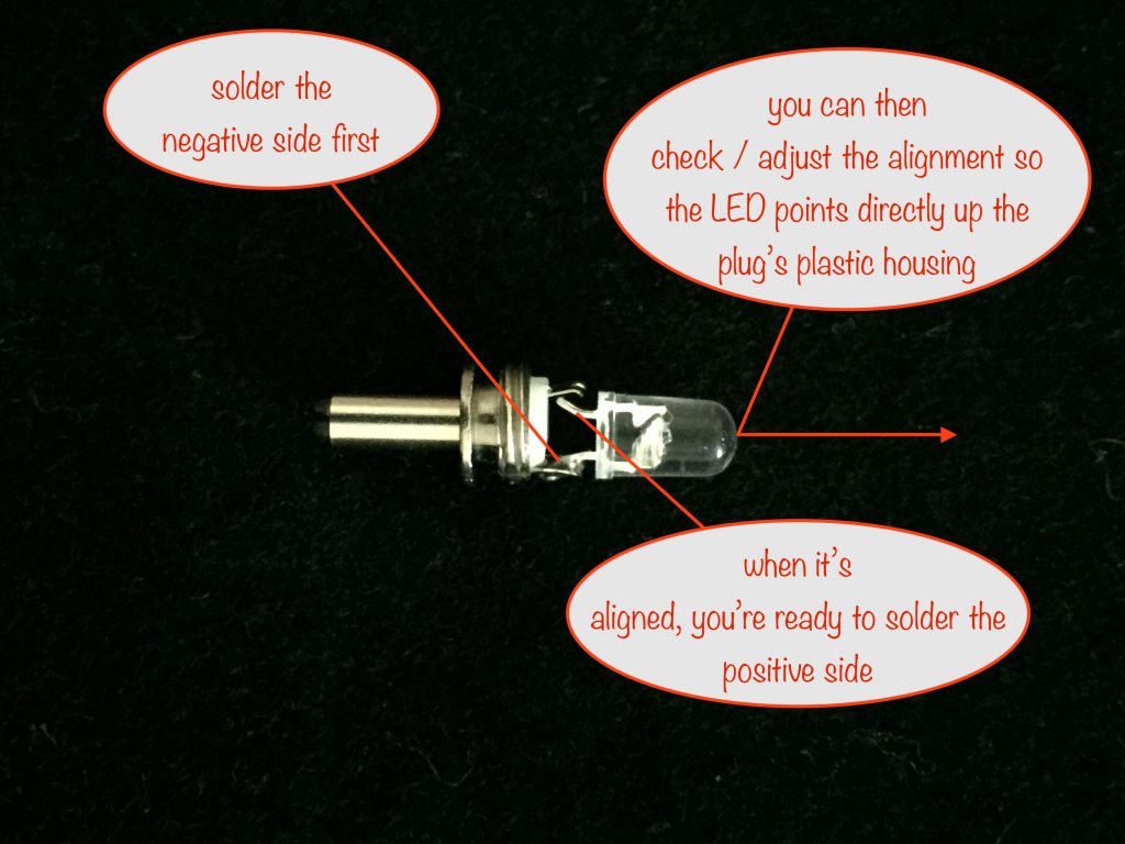
Once you’ve soldered the first leg, you have a chance to bend the LED into alignment so it points directly up the plastic housing.
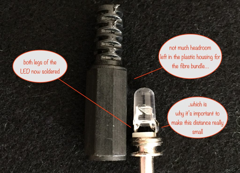
Here’s the LED with both legs soldered shown next to the plastic housing, You can see it’s aligned ok and also see just how little room there is left over for the fibre bundle.
Making the fibre bundle
Get a 2mm length of 4.8 mm heat shrink tubing and place it on the shaft of your 4.5mm drill bit. Roll it over the shaft of your hot soldering iron so it shrinks in size to fit. You’ve now got your collar for the fibre bundle.
Next, take a small handful, 10 or so, of your 5mm lengths of 0.75mm fibre and slide them down the opening of the plastic housing from one of your 1.3mm DC plugs.
Slip your heat-shrunk collar over the ends.
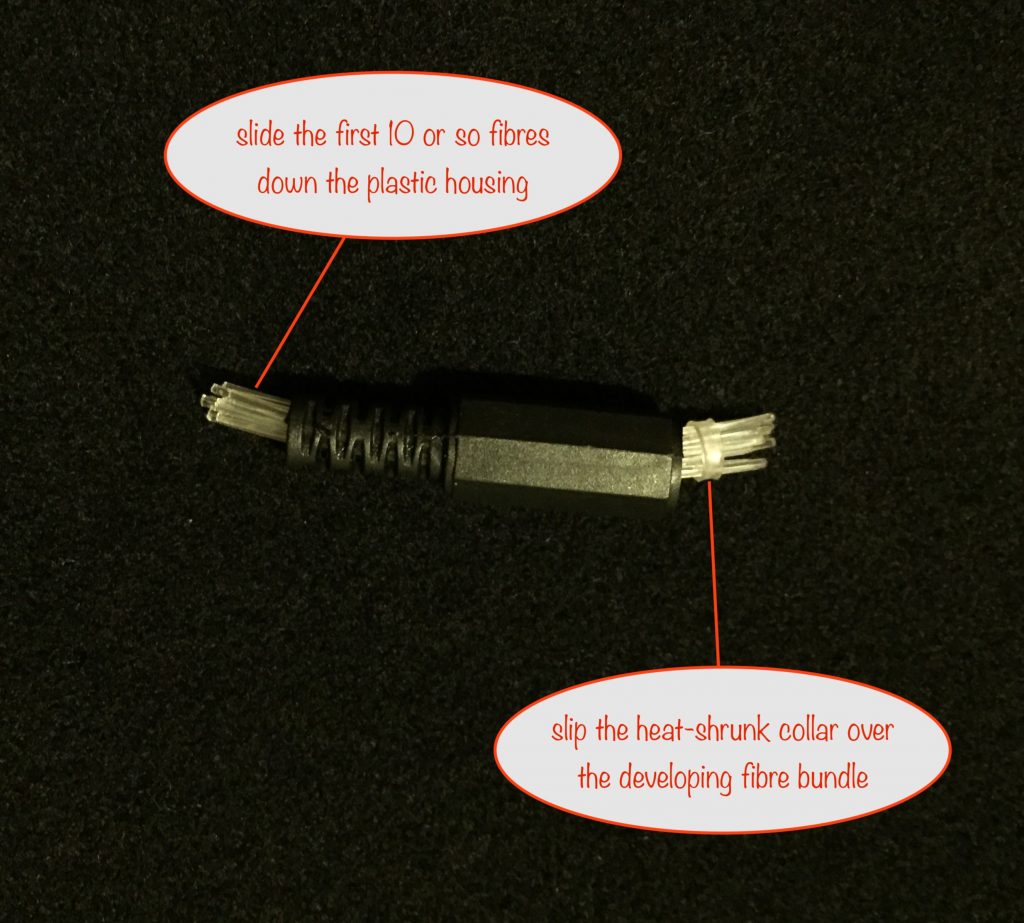
It can be a bit fiddly to get the rest of the fibres into place but I find it’s easier if you slide them down the centre of the developing bundle. The last two or three are the trickiest but once you’ve done it, you’re almost there.
All you have to do now is line up the ends.
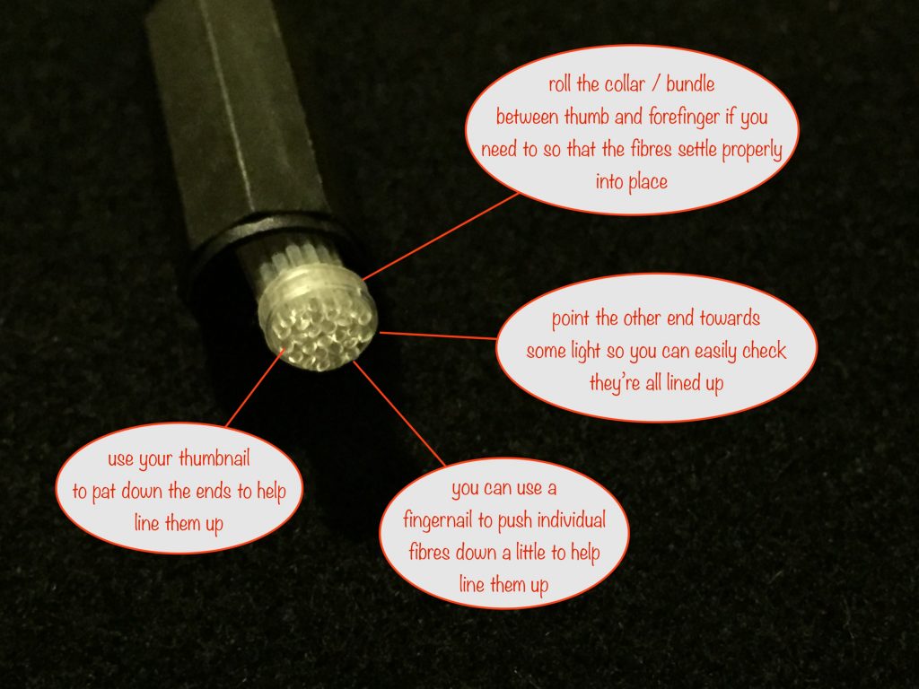
If you point the other end of the fibres towards a light source, it’ll make it much easier to see the ends and align them to each other.
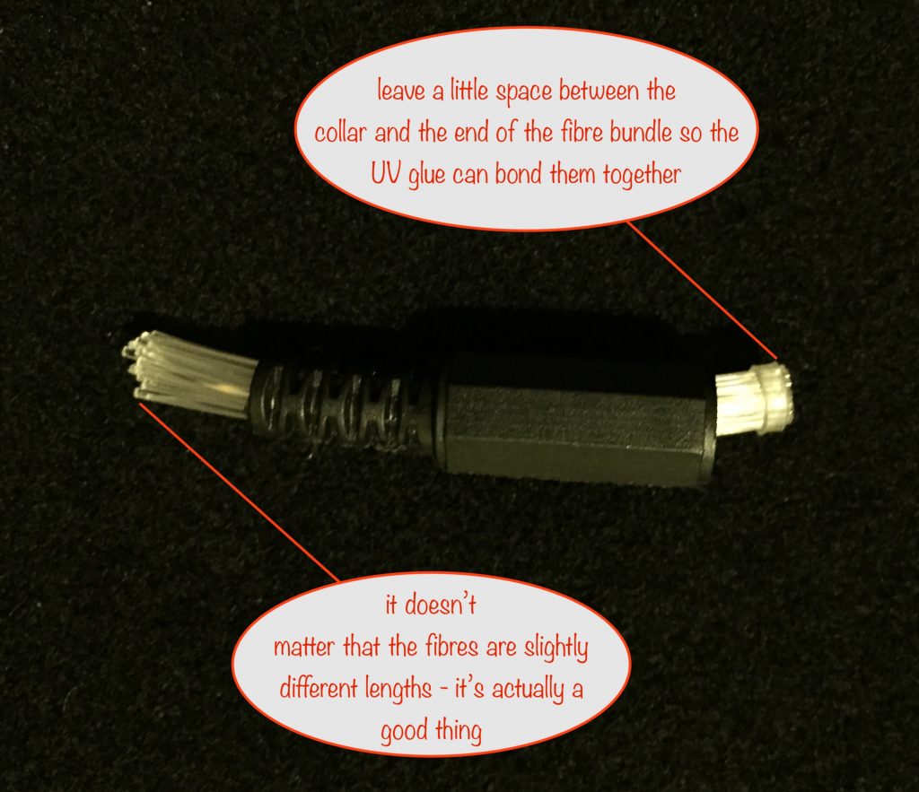
Once you’ve lined up the ends and left a small gap between them and the collar, you’re ready to bond them together with UV glue.
UV gluing and finishing the Mini Sparkle
Apply a little UV glue all the way around the gap between the collar and the ends of the fibres, overlapping with the collar a little. Then apply the UV glue to the ends of the fibres and set with the UV LED.
Once that’s done, you can slide the fibre bundle up inside the plastic housing until you feel it bump up against the top. Point the other end of the fibres to the light and look down the housing to make sure it’s properly seated at the top.
When you’ve done that you can screw the LED and plug assembly into the housing and tighten it up. If you’ve made everything compact enough, you should feel a little movement if you try to push the fibre bundle back into the plastic housing.
Splaying out the fibres
To complete your first mini sparkle, you need to splay out the ends of the fibres.
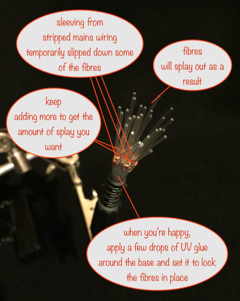
Grab some old 13A mains cable and expose the inner wire. Strip the sheathing from one of the wires and cut into 2 or 3mm lengths. Slip these over some of the fibres and work them down close to the bottom, using a small watchmakers screwdriver to help. I find that using the fibres close to the middle of the bundle works best for this.
Keep adding them until you’ve got the amount of splay you want. When you’ve done that put a little UV glue all the way round the base and set it to lock the fibres in place. Be careful to avoid the sheaths!
Once you’ve done that, slip the sheathing off the fibres and you’re done.
Now you can do the other nine 😎
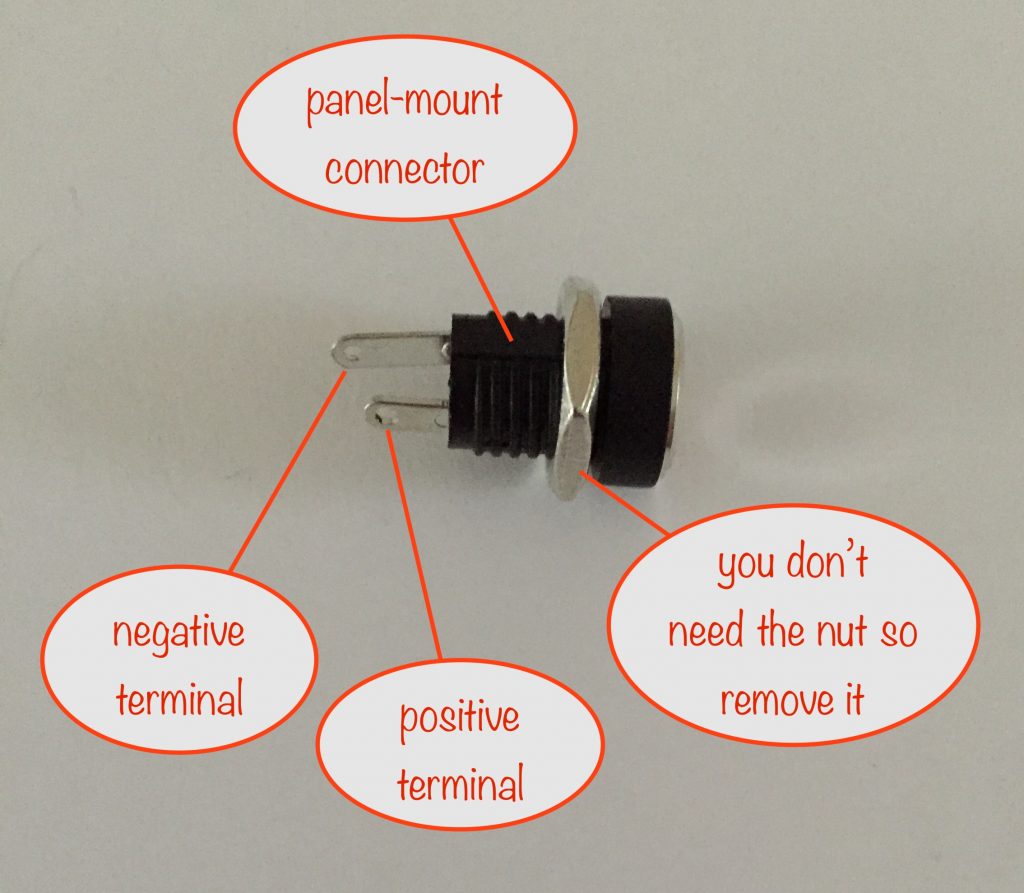
Soldering the panel-mount connectors and lead
Each mini sparkle plugs into a panel-mount connector, so you need to connect them up using the 20cm lengths of lead that will supply the power.
So take two lengths of your silicone wire, strip one end of each. Twist the exposed wire of the two black ends and solder them together. Do the same for the red.
Note that for this first one, one of the free ends will be used later for the power-in connector and, when you reach the last one, the free end will be used for the power-out connector
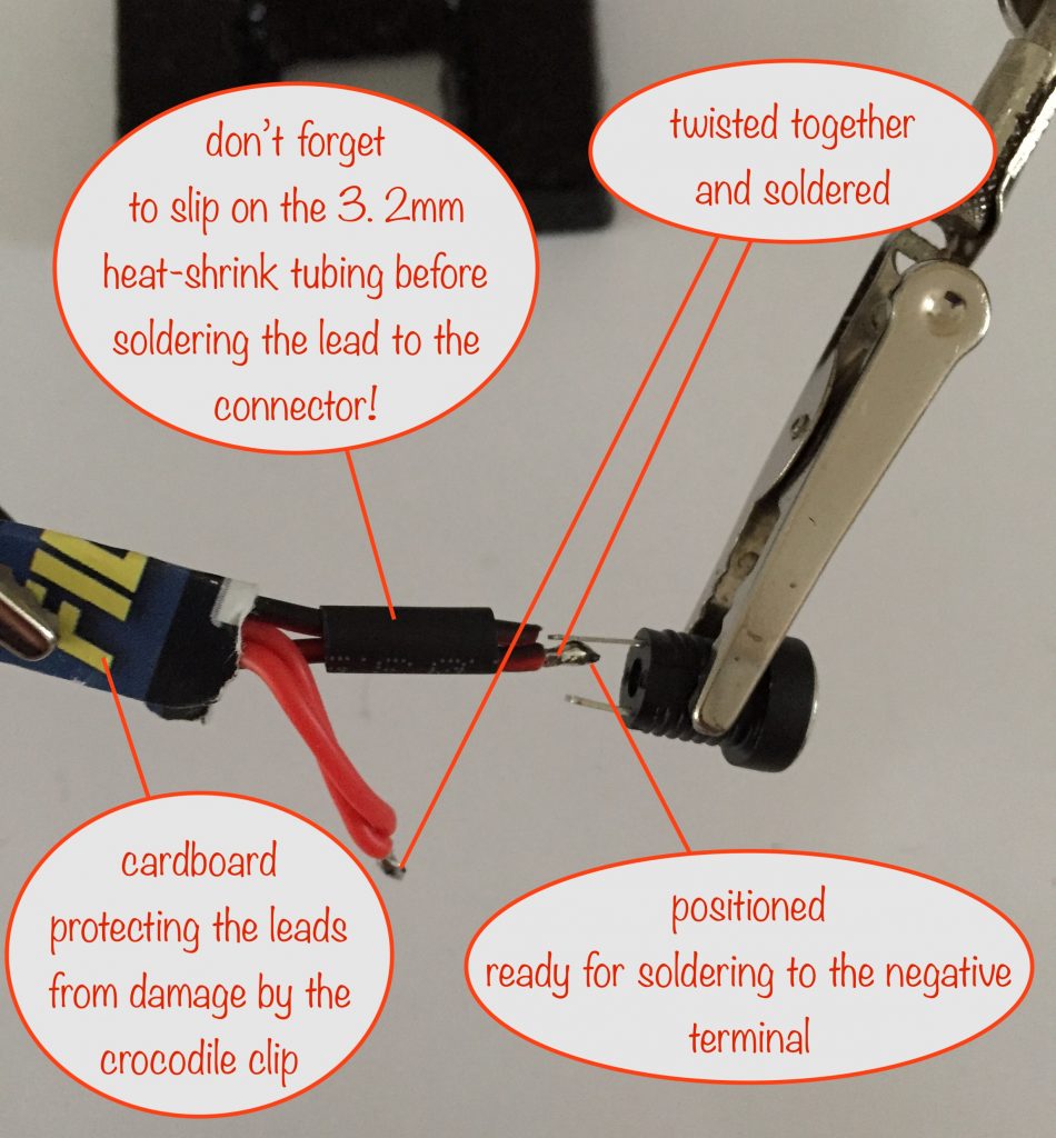
Once soldered, the 3.2mm heat shrink tubing is used to prevent shorting between the terminals. So go ahead and solder the black wire to the negative terminal. Slide the heat-shrink up and shrink it with the barrel of your soldering iron.
Now solder the red wire to the positive terminal.
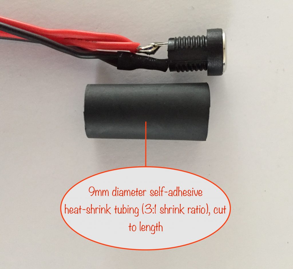
The self-adhesive 9mm heatshrink tubing is large enough to slip over the panel-mount connector. It’s used for strength and also seals up the connector’s terminals to prevent them shorting with anything else.
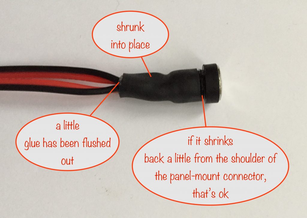
So do that and then shrink it in place, holding it so it’s at the top of the panel-mount connector’s screw threads. As usual, use the barrel of your soldering iron. Shrink the rest by rolling the barrel of your soldering iron towards the wires for a neat finish and to flush the glue out a little.
You’re now ready to hook up the next length and panel-mount connector.
Power in and out
When you’ve done all ten, the completed string needs a power-in connector at one end and a power-out connector at the other. So hook up the connector type you’ve chosen.
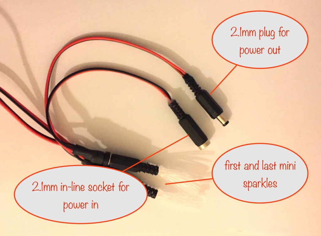
For power-in I’m using a 2.1mm in-line socket and for power-out (to allow more than one string to be strung together) a matching 2.1mm DC power plug.
I use similar connectors for all indoor modules so I can mix ‘n match.
Enjoy what you’ve just made! 😎
Other projects in the Nifty Hobby Projects for LEDs and Solar series (so far, more to come very soon):
- Flasher Memory Aid
- Dark-activated Switch
- 5 LED String
- Fibre Optic Display
- Solar Lithium Ion Battery Charger
- Solar NiMH Battery Charger for 2 AAA batteries
- Solar NiMH Battery Charger for 2 AA batteries
- Solar NiMH Battery Charger for 6 AA batteries
- Timer-delay Off Switch
- 4-LED Porch Light
- 10-LED Bedside lamp
- Mini Camping / Bedtime Reading Lamp
- Main page with links to where to buy stuff