this simple battery pack project is for 6 rechargeable AA NiMH batteries, specifically for powering a 3W (or less) LED lamp and is another module in the Nifty Hobby Projects for LEDs and Solar series
Written by team-member Mark Ridley
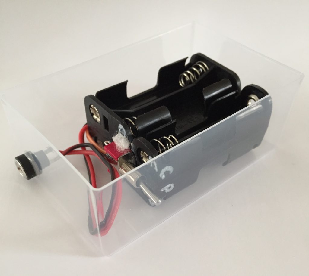
It uses two stacks of 3 AA NiMH rechargable batteries. The stacks are connected in parallel when being used and are connected in series when being charged by the solar-powered charger.
If you use 2900mAh batteries and are powering a 3W LED lamp you should get 6 hours use out of it. With a 1W LED lamp you’ll get around 18 hours use.
Schematic
This shows how the battery stacks and charge/power switch are wired:
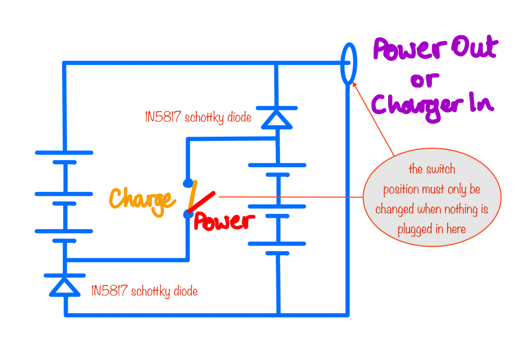
with the stacks connected in parallel
When you’re ready to use the battery pack to power your LED lamp (max 3W), you set the switch to the “Power” position and only then do you plug in the LED lamp.
When it’s time to recharge the battery pack, you first unplug it from the LED lamp. Then you flick the switch to the charge position and, when you’ve done that, you plug in your solar-powered 6 AA NiMH battery charger.
Wait… what charger? It’s the charger you built in this Nifty project, slightly modified to make it easy to plug in to the battery pack. See a little later for details.
How does it work?
when being charged, the switch is closed so the stacks are connected in series
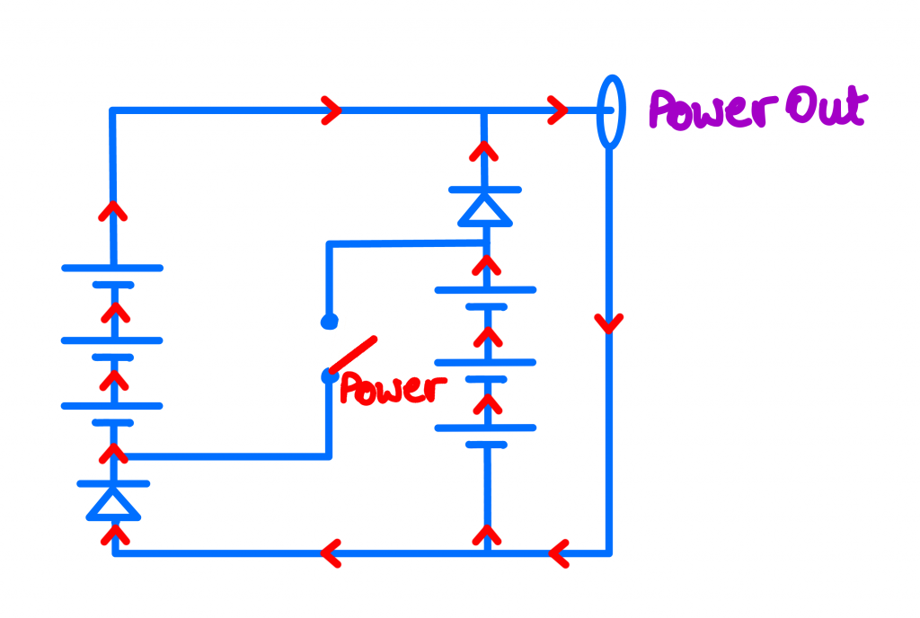
Power mode
The schematic on the left shows the direction of current flow when the battery pack is powering the LED lamp. The two stacks are connected in parallel in this mode.
The diodes are 1N5817 schottky diodes, chosen for their low voltage drop of around 0.45V. Connected as they are, the voltage of each battery stack will be:
3.6V – 0.45V = 3.15V
which is fine for the suggested LED lamp.
The diodes ensure that if the voltage across the stacks become unbalanced as they discharge, there will be no current flow out of one stack and into the other.
Note that the 1N5817 schottky diode is rated at 1A (ave) and that’s why the LED lamp it powers shouldn’t be more than 3 watts. A 3W LED has a recommended current of 850mA or thereabouts.
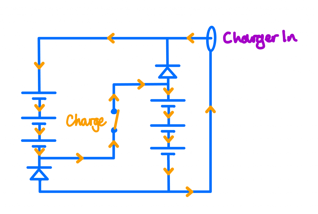
Charging mode
When the battery pack is being charged, the schematic on the right shows the current flow. This time the stacks are connected in series by the closed switch.
In this mode, the diodes enforce the series connection of the batteries by preventing current from flowing where it’s not wanted.
Note that there’s no need to worry about balancing the batteries because they’re being charged in series. If one cell has a lower voltage than the others, it’ll need more time to charge so the others will all get charged for longer. That’s not an issue because the charging current used is C/10 as recommended by the battery manufacturers.
Making the pack from battery holders
It’s easy to get confused when translating the schematic into a correctly soldered set of wires and diodes, so follow the photos carefully.
Double and triple check everything before you even think of applying solder. And make sure you slide on the heatshrink tubing before connecting anything each time!
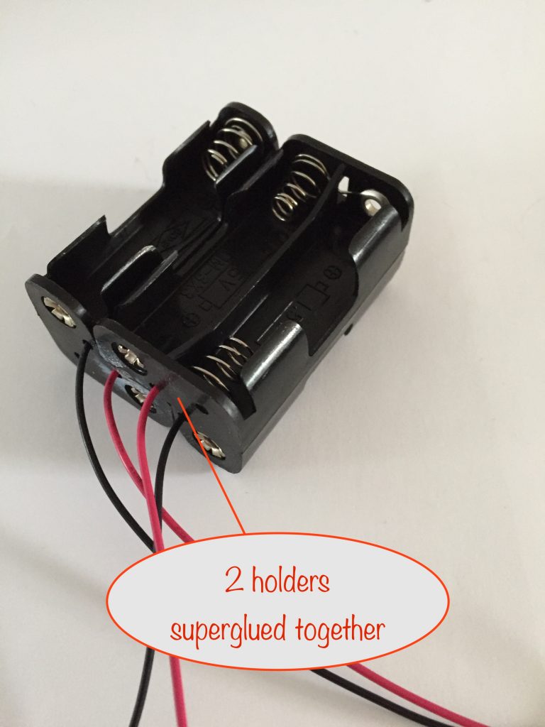
One battery stack goes in each holder and, to help with describing things when they’re glued together, I’ll label what I’ll call the front and back views.
When viewing the front, the left hand holder corresponds to the left hand side of the schematic and vice versa.
Gluing the holders together
The first step in making your 2 stack, 3 AA NiMH per stack battery pack is to glue the two L-shaped battery holders together.
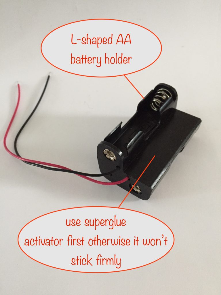
The only glue I’ve found to be effective with this sort of plastic is superglue but only when used with an activator. Loctite have one – available here from ebay.
Dealing with the bottom half of the schematic
In the next step we’ll deal with the negative leads, diode and one of the wires for the switch – everything from the bottom half of the schematic.
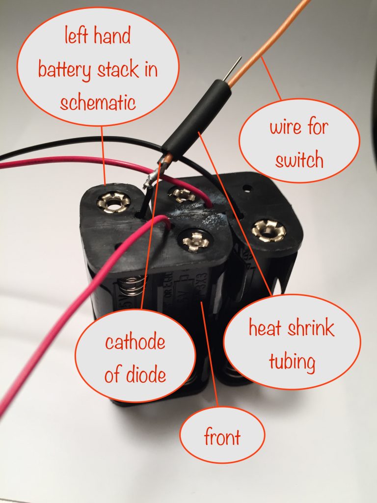
In the above photos you’ll see how the negative leads, the diode and one of the switch wires are soldered together.
Once that’s been done, as you’ll see in the next photo, the black heatshrink tubing has been shrunk to insulate the soldering.
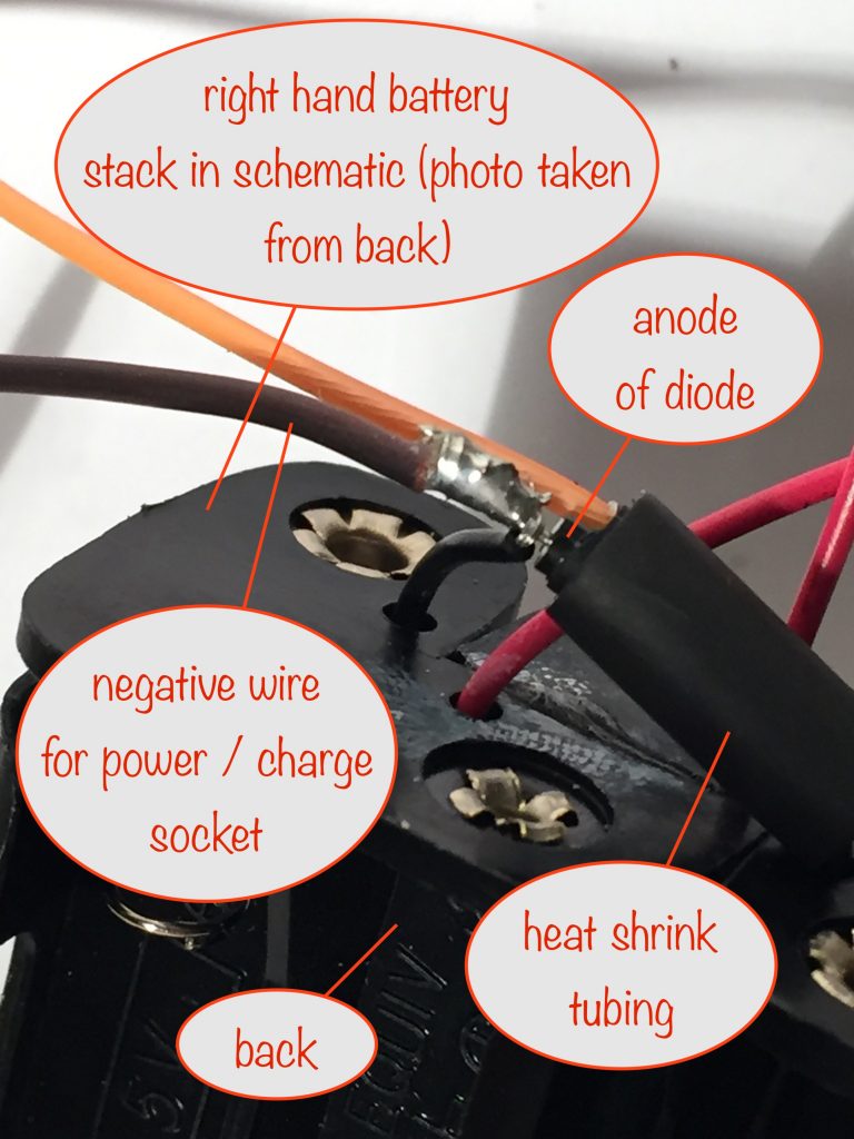
Dealing with the top half of the schematic
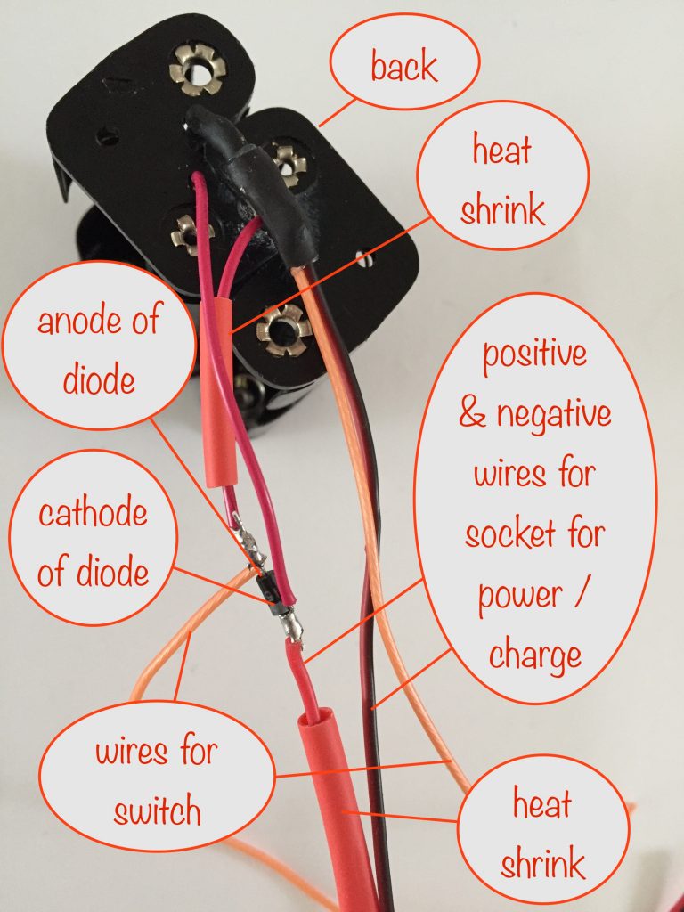
Here, the positive lead from the right hand side of the schematic is connected to the anode of the diode and the positive lead from the left hand side is connected to the diode’s cathode.
The cathode is then connected to the positive lead that, in turn, connects to the power-out / charge-in socket.
Now slide the red heat shrink tubing into place and apply your soldering iron shaft to it so everything is well insulated.
The next step deals with the switch and tidying up the wires.
Soldering and supergluing the switch
As before, you’ll need to use the activator as you’ll be supergluing the switch to the plastic.
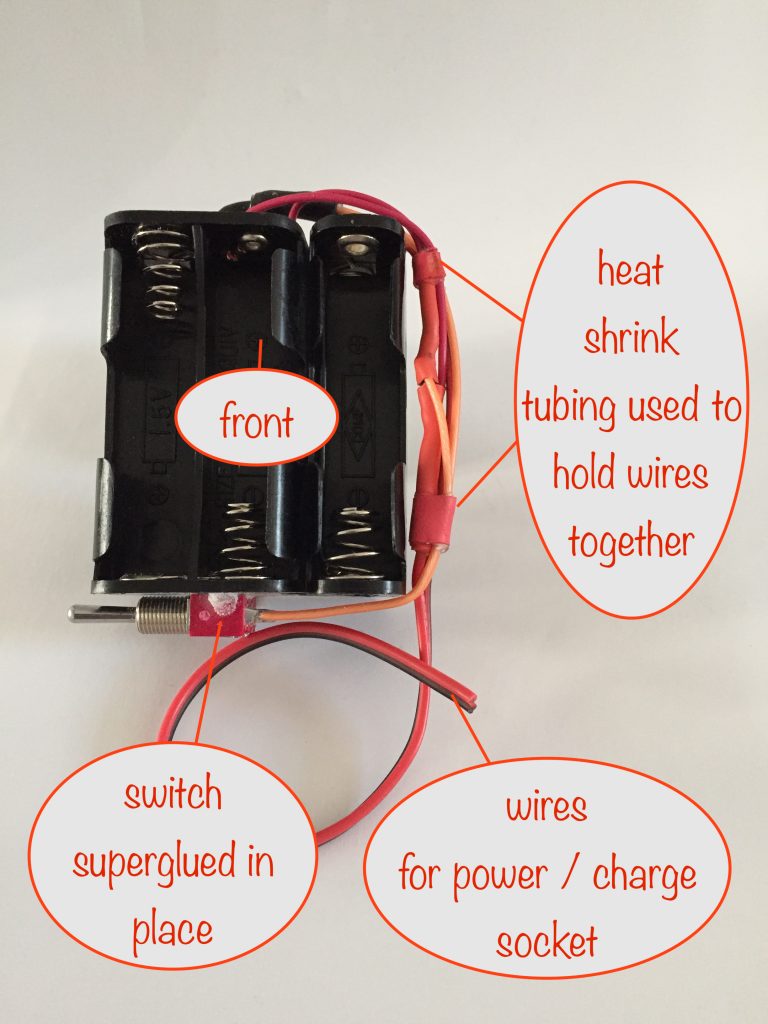
Once the superglue has initially taken (give it about 10mins) give it additional strength by using adding more superglue around the switch and then sprinkle on some baking powder.
When you add baking powder in this way, it reacts with the superglue to form a plastic that’ll go rigid after around 10 minutes or so.
At this point you can slip on a couple more pieces of shrink wrap tubing to hold the wires together and then shrink then in place as per the photo.
You’ll need to give it 24 hours to set completely but after an hour it’ll be firm enough that, with care, you’ll be able to solder the wires to it without dislodging it.
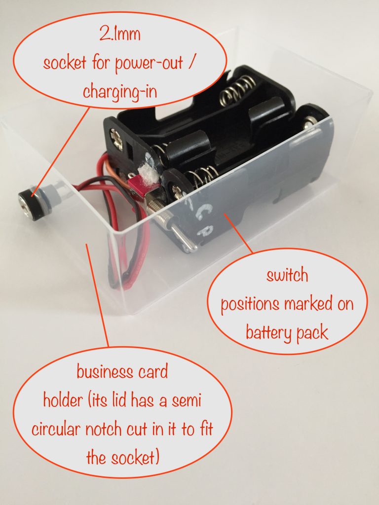
Use a tester to confirm which way the switch lever needs to be for the switch to be open. Then use a white marker pen or equivalent to mark that position as “Power” and mark the opposite position as “Charge”.
You do this because it’s vital to set it correctly so you don’t blow the LED lamp by connecting it up when it’s in the wrong position.
If you accidently use it for power when it’s in the charge position, you’ll get 9V at the socket with the result that your LED lamp won’t be able to handle it and will die.
Soldering the socket
I’m using business card holder boxes for my battery packs. Whatever you use for yours, don’t forget to first put the socket’s nut over the wires before pushing them through the hole from the inside.
Now, about that charger…
Here’s a link to the charger build project and this is what it looks like filled with batteries as it was originally intended to be used:
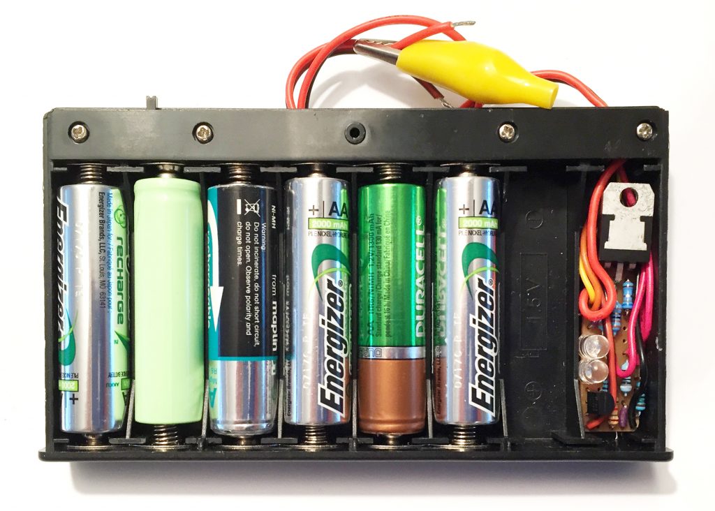
Here it is modified for use with the battery pack:
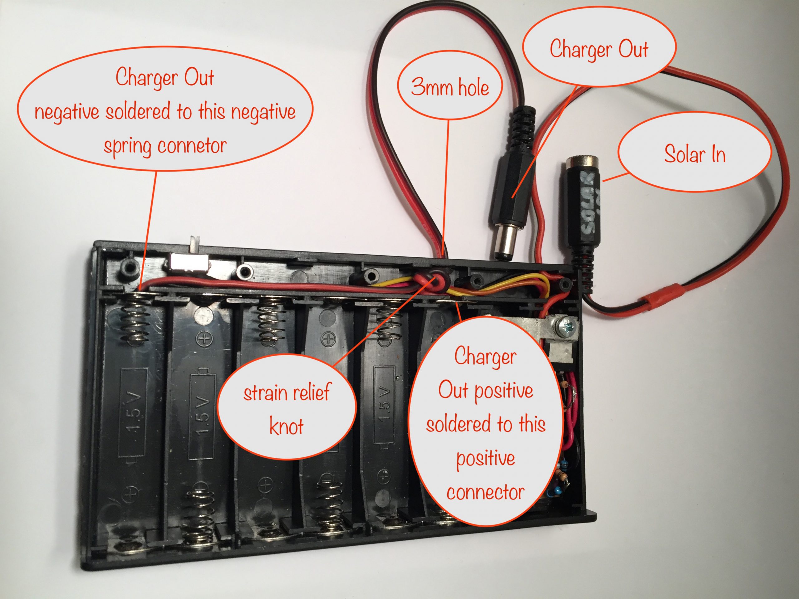
I’ve modified the charger to include an output lead and 2.1mm plug so that the charger can be plugged into the LED lamp battery pack to charge it.
It was a simple matter of:
- drilling a 3mm hole in the battery box where indicated
- threading the twin lead from the outside and through the hole to the inside
- tying a strain relief knot in the lead
- soldering the negative lead to the battery box negative spring connector
- soldering the positive lead to the indicated positive connector
- soldering on the 2.1mm dc connector
Make sure you do it in that order because threading the twin lead through the hole can be a right pain if you wait until later in the sequence to do it.
If you’re going to use 2900mAh batteries, their manufacturer recommended charging current is a little under the normal C/10 – they recommend 270mA. To set that current, swap out R1-1 or R1-2 for a 4.7Ω 1/2W resistor.
With 2900mAh batteries you’ll get 3.6V+(2*2.9A) = 20W
Remove any batteries from the charger module before using it to charge your battery pack. If you leave the batteries in, then they will dump their charge straight into the battery pack, leading to very high currents and likely killing all the batteries.
In conclusion
That’s it, well done for reaching here. Hopefully your build went smoothly!
As it takes a day of sunshine to fully recharge a pack, why not build two?
It’s even possible to plug your solar panel into two chargers at the same time, so why not build 2 of them? All you need is a 12V solar panel rated at 7W or more.
I’d love to hear how you got on, so please leave a comment 😎
Other projects in the Nifty Hobby Projects for LEDs and Solar series (so far, more to come very soon):
- Flasher Memory Aid
- Dark-activated Switch
- 5 LED String
- Fibre Optic Display
- Mini Sparkles Colour-changing LED Fibre Optic String
- Solar Lithium Ion Battery Charger
- Solar NiMH Battery Charger for 2 AAA batteries
- Solar NiMH Battery Charger for 2 AA batteries
- Solar NiMH Battery Charger for 6 AA batteries
- Timer-delay Off Switch
- 4-LED Porch Light
- 10-LED Bedside lamp
- Mini Camping / Bedtime Reading Lamp
- Main page with links to where to buy stuff
Read all about NiMH rechargeable batteries on the Wikipedia Nickel-metal hydride battery page (opens in new tab / window)