this fibre optic display is another module in the Nifty Hobby Projects for LEDs and Solar series
Edit: Changed the Finishing Off section to use a much better way of stabilizing the battery box


The hard thing to do with LEDs and fibre optics is connecting them together so they stay together! The other hard thing to do is to get them to splay out so you get a pretty display.
Don’t worry, both are solved in this build tutorial 😎
First off, a word of warning: DON’T be tempted to use superglue. The reason is that it makes the plastic used to make the fibres so brittle that they crumble and break when you so much as look at them!
Features of Module
- Looks really cool and pretty!
- 5 fibre bundles driven by 5 colour-changing LEDs all mounted on a pp3 battery box
- 30 x 0.75mm fibres for each bundle
- designed to be used with the Dark-activated Switch module
- the switch on the battery box switches LED fibre display off
- can be powered directly by a 3.7V Lithium Ion battery or 3 NiMH batteries in series
Components list
- 5 x 5mm colour-changing LEDs
- 30m of 0.75 diameter plastic fibre optic cable, cut into:
- 90 lengths of 19cm (3 fibre bundles for the back – longer to overlap the ones at the front)
- 60 lengths of 18cm (2 fibre bundles for the front)
- clear 4.88mm diameter heat shrink sleeving (I’ve used clear and black in the photos to make things obvious) cut into
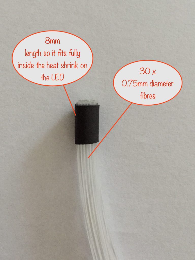
- 5 lengths of 8mm – fibre bundle collar
- 5 lengths of 22mm – LED sleeve
Tools etc. you’ll need:
- 18 Watt soldering iron, 25 Watts at a push
- “Helping Hand”
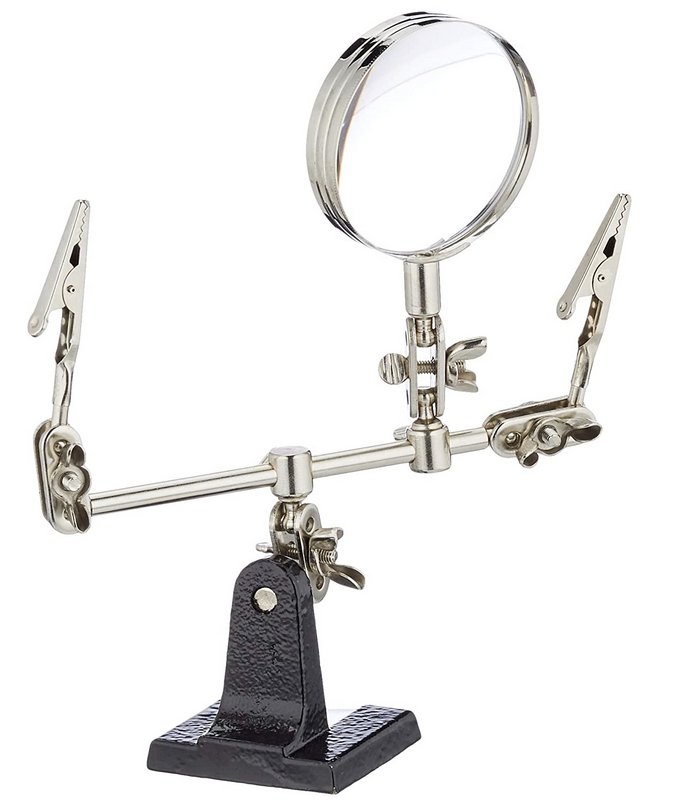 – invaluable aid while soldering or gluing
 - Wire strippers covering 26 to 16 AWG
- Side cutters
- Small snipe-nose / needle-nose pliers
- Craft knife for cutting fibres
- Glue gun with black glue sticks for fixing everything in place
- Neodymium magnet (optional) to weight down / hold the battery box in place
or some heavy metal washers
or you could fill a small resealable (ziplock) bag with sand - UV-glue for helping to hold the fibres / LED together
- Small hobbyist drill with 2mm, 3mm, 4.5mm, 5mm and 6mm drill bits
Preparing the battery box
Stripping it down
There are two types of PP3 battery boxes commonly available that are ideal for this project:
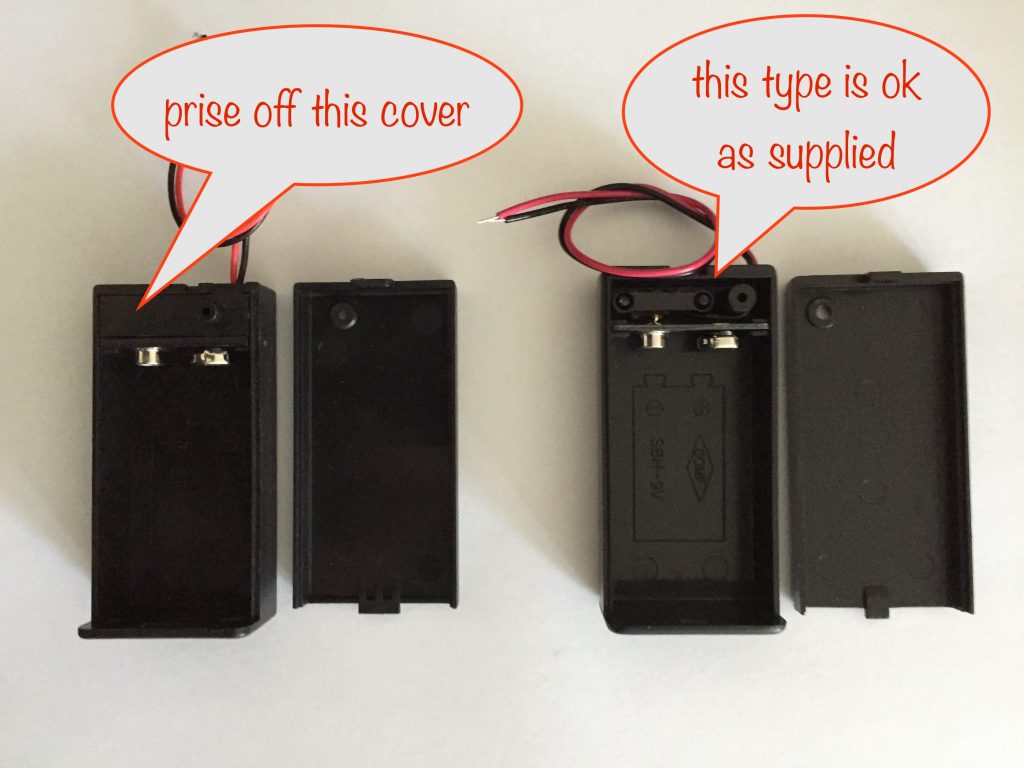
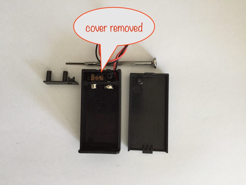
If you have the type on the left, carefully prise off the cover with a small watchmaker-style flat-bladed screwdriver to reveal the switch and wires. You can then put the cover into your recycling bin as it’s of no further use.
Whichever type you have, you now have to pull the wires out of the hole and back into the box. Push them through the hole until you can grab them and pull the rest of the way.
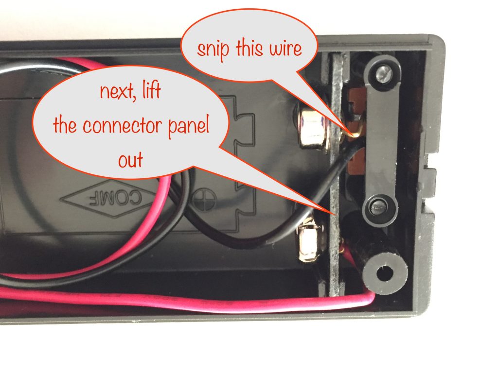
Use your side-cutters to snip the exposed wire connecting the switch to the negative battery terminal. This means the switch won’t be held firmly in place – see below for how to fix that.
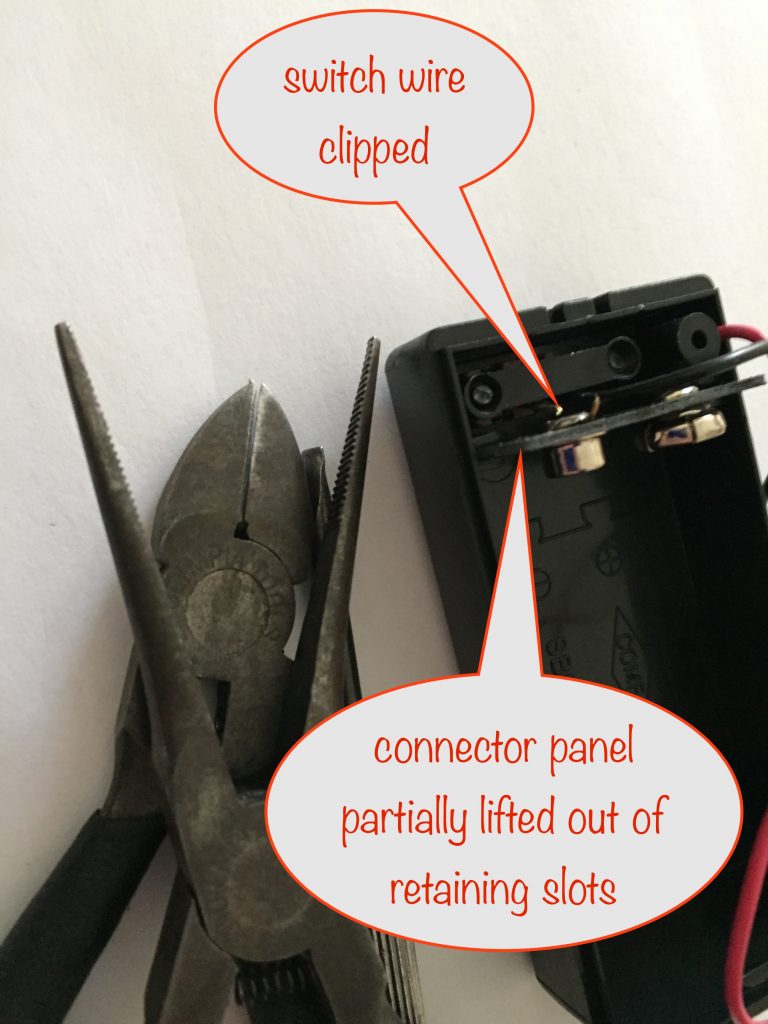
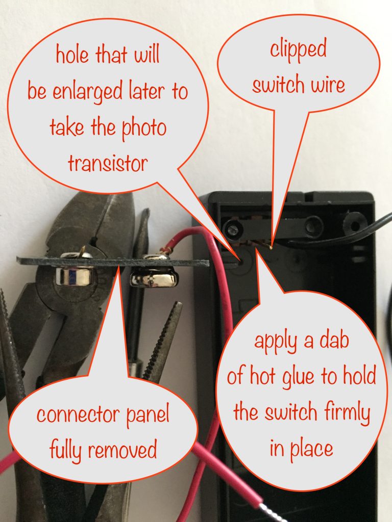
Now use your snipe-nose pliers and a larger watchmaker’s screwdriver to pull and lever the plastic panel holding the battery connections out from its retaining slots. You don’t need it anymore so put it into your box of bits for a future project.
When you’ve done that, you’ll need to secure the switch in place with a dab of hot glue.
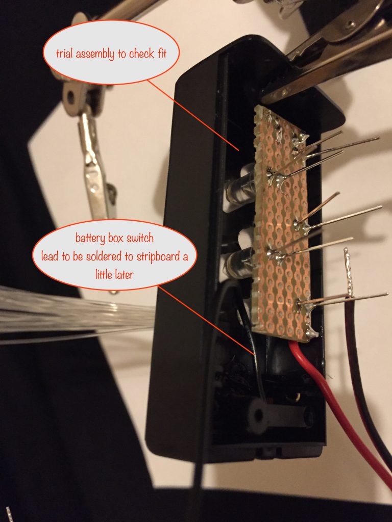
Leave the black wire that’s connected to the switch – you’ll make use of it later.
Preparing your fibres
For each bundle you’ll need 30 fibres cut to 19cm lengths for the three back bundles and 18cm lengths for the two front bundles
Preparing a fibre bundle
Preparing the collar
Take an 8mm length of 4.8mm heat shrink sleeving and put over the end of a 4.5mm drill bit and shrink it so it’s a snug fit.
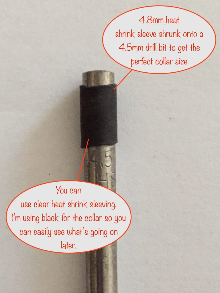
This will give a collar that perfectly holds 30 fibres nice and tight. I’ve used black sleeving here so you’ll be able to see easily what’s going on a little later.
Inserting the 30 fibres
Insert most of the fibres and get the ends lined up with the edge of the collar. The last two or three fibres will be quite tight. Roll the collar as you go between thumb and finger to jiggle the fibres into place.
Checking all are present
It’s quite easy for you to miss getting a fibre all the way to the end. I know, because it happens to me all the time when preparing bundles. They do like to hide!
So here’s how to check they’re all present and correct at the edge of the collar.
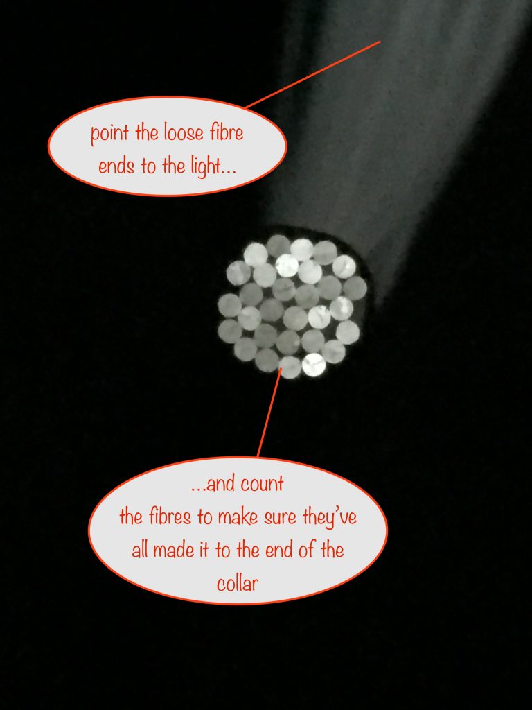
If you point the loose ends of the fibres towards the light, the ends by the collar will light up and they’ll be much easier to count.
If any are missing, remove a couple of fibres so it’s easy to slip the collar back and find where they’re hiding. Bring their ends to the front, slide the collar to the ends and put back the fibres you removed.
Preparing the LED end of the fibre bundle
Get one of your 5mm colour-changing LEDS (test that it works!) and slip a 22mm length of clear heat shrink sleeve over it as shown. It’s can be a tight squeeze to get it over the shoulder of the LED but it will go with gentle persuasion.
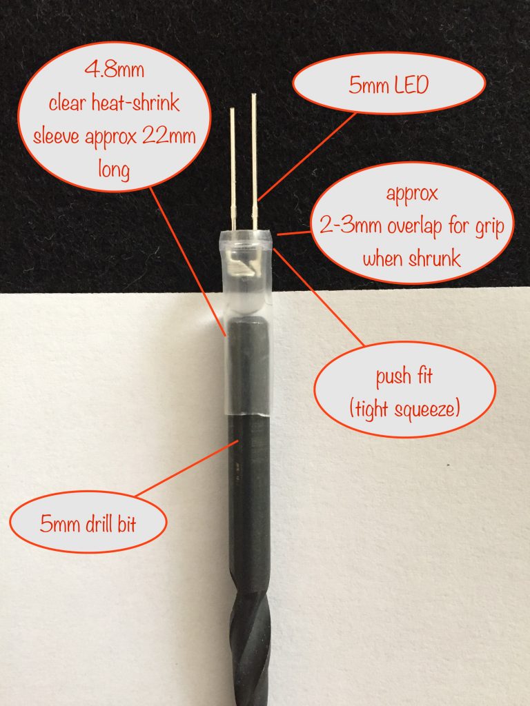
Overlap the sleeve on the shoulder by 2 or 3mm to make sure it grips well when shrunk.
Insert the shank of a 5mm drill bit into the other end to help you when you do the shrinking.
You can now switch on your soldering iron and, when it’s hot, roll the LED end of the sleeving back and forth over the shaft of the soldering iron.
The goal here is to get a nice tight fit around the LED so the UV-glue, when added later can’t leak out around it.
Be very careful not to shrink the sleeving beyond the tip of the LED!
Here’s what it looks like once shrunk around the LED
If you look closely, you’ll see that the sleeving is now shrunk to grip the LED tightly. The rest of the sleeving will be shrunk later when you’re mounting the bundles in the battery box.
Check the fit
Slip the collared bundle of fibres into the unshrunk portion of the sleeving on the end of the LED. This is a final check to make sure it’s going to be a snug fit when you assemble everything.
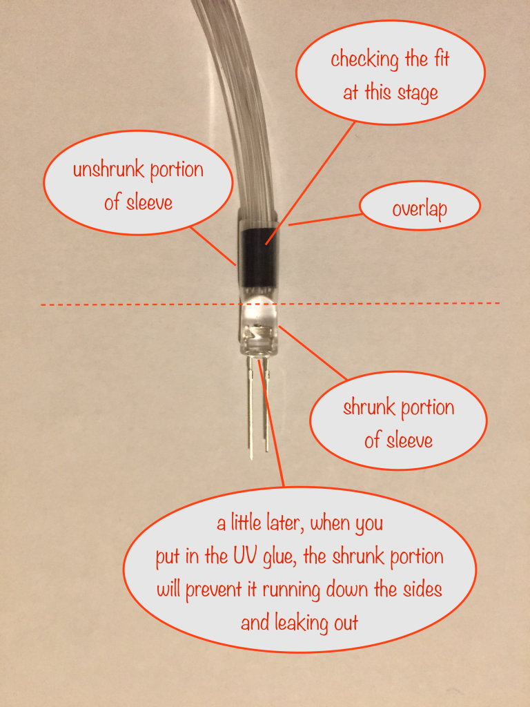
It’s important that the sleeving extends beyond the collar so that, when it’s shrunk, it holds the collar in place.
Drilling the fibre bundlle holes in the battery box
Now is a great time to drill the battery box. Doing it now will give you an idea of the practicalities involved in assembling everything.
Brass rubbing
What? This is a neat way of marking out where the centre of the fibre bundle holes are to go.
The stripboard you’re going to use to mount the LEDs needs to be 17 holes wide and five deep. I’ve used a larger piece I had hanging around for this part as the exact size doesn’t really matter at this point.
Grab a sticky label and reduce its stickiness by sticking and peeling off from your fingers a few times – enough so it’s still got some stick but not so much that you won’t be able to get it off the stripboard in a minute.
Stick it to the stripboard and take a soft pencil and rub over the size needed. This will reveal the holes. Now peel it off the stripboard and stick it to the upper (switch) side of the battery box.
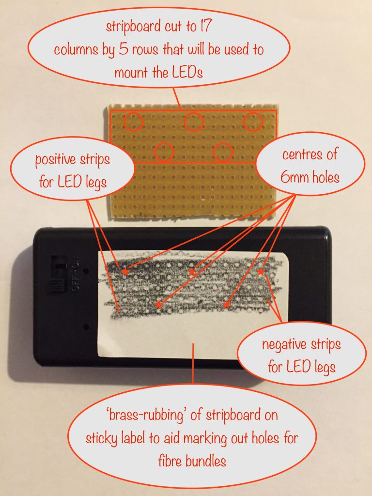
Now you’re ready to mark off the centres of the holes for the fibre bundles. It makes sense to me to place three at the back and two at the front so that the fibre bundles curve and hang over the body of the battery box, so heping with stability.
To mark the hole centres I use a screw’s point, pressing down hard. This gives a small indent to stop the drill bit drifting off.
So it’s time to drill. Remember to start with your smallest drill bit and work up the sizes to the final 6mm drill bit.
The assembly can be quite tricky so the more accurately you position the holes now, the better!
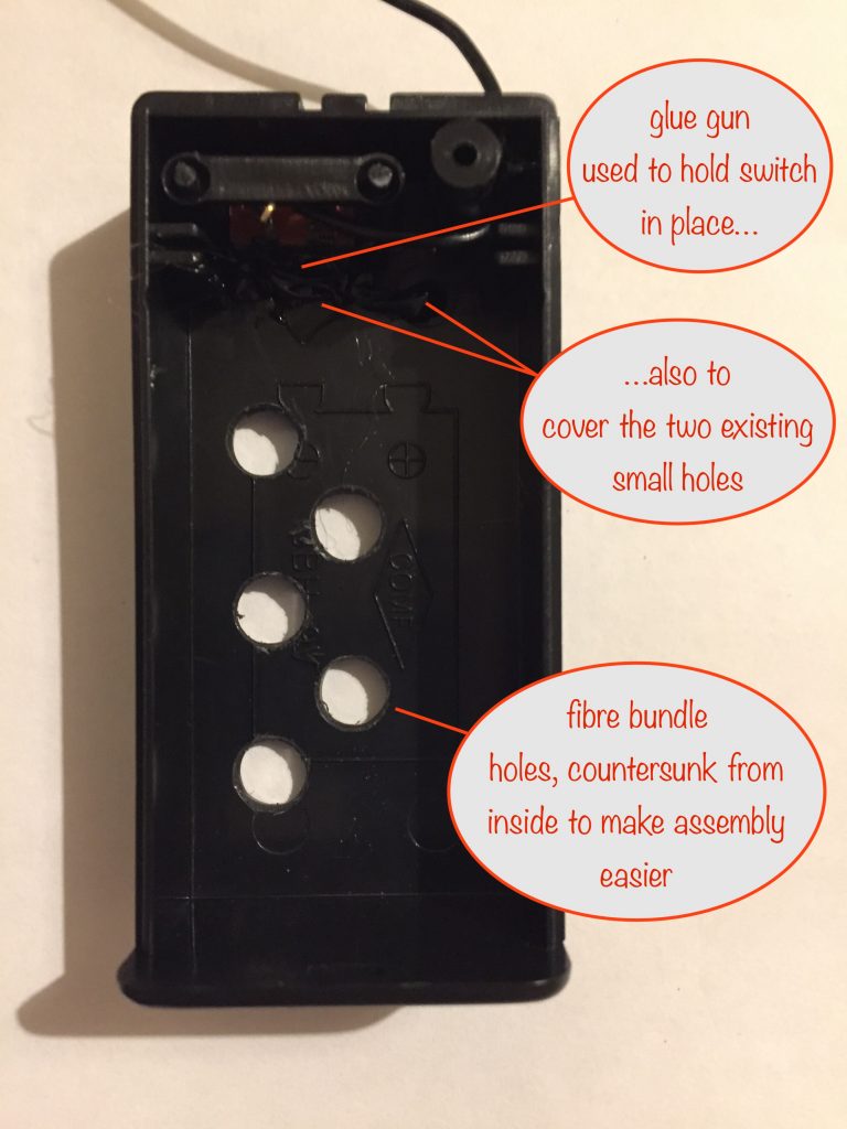
Once you’ve drilled the holes, countersink them from the inside. This will make it much easier to fit the stripboard once the LEDs with their sleeving in place have been soldered.
Soldering the stripboard
Now’s the time to get down and dirty with the stripboard.
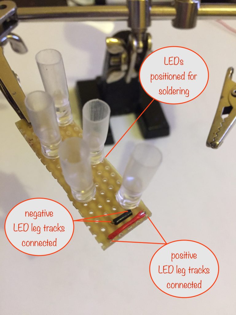
First cut some red wire to size and use it to connect the outer rows that will hold the positive legs of the the LEDs.
Do the same with black wire to connect the inner rows that will hold the negative legs of the LEDs.
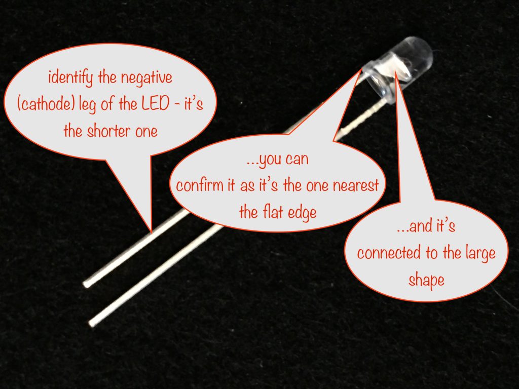
Now insert the LEDs, being careful to get the orientation right. Here’s how to identify the negative leg and, by elimination, the positive leg.
The way I’ve designed things the outer rows take the positive legs of the LEDs and the inner rows are for the negative legs.
With the LEDs inserted as close to the board as possible, bend their legs outwards at an angle of 45° to hold them in place. Turn the stripboard half way round and solder only one leg of each LED for now.
Visually inspect the LEDs to check that they’re butted up against the stripboard and they’re as near-vertical as you can make them. This will help you when you come to assemble everything.
If you need to make any adjustments to get them right, now’s the time before you solder the second leg of each.
With the second legs soldered, everything should now be firm and accurately placed ready for assembly.
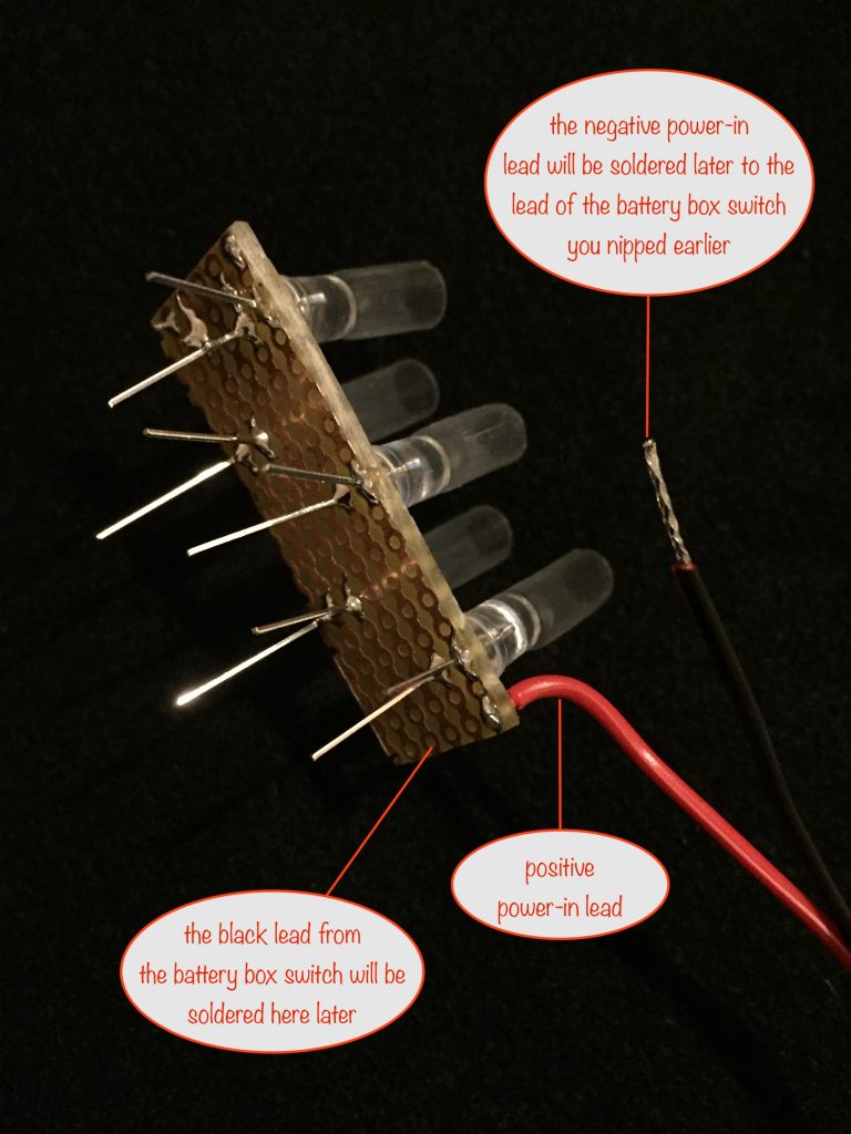
Before doing that you need to prepare whatever leads you’re going to use to supply power to the module. I’m using twin flexible red-and-black leads so I’ve stripped and tinned the ends. Next I soldered the positive (red) lead to one of the positive tracks at the end of the stripboard that will go nearest the switch of the battery box.
Now that’s done, it’s time to make sure everything fits together.
Trial Assembly
With the countersunk fibre bundle holes and the accurately positioned and dead-vertical soldered LEDs, it shouldn’t be much of a juggle to fit everything together in this last check.
Now that we’ve made sure everything fits together, we can do the assembly for real.
Final Assembly
Inside of battery box assembly
Before following these steps, apply power to the stripboard to make sure all the LEDs work. It’s much easier to fix anything now than after after you’ve assembled things!
Steps:
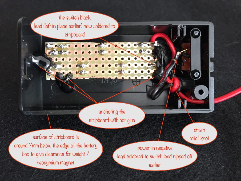
- solder the battery box switch lead (black) to the stripboard
- nip all the LED legs as close to the board as possible
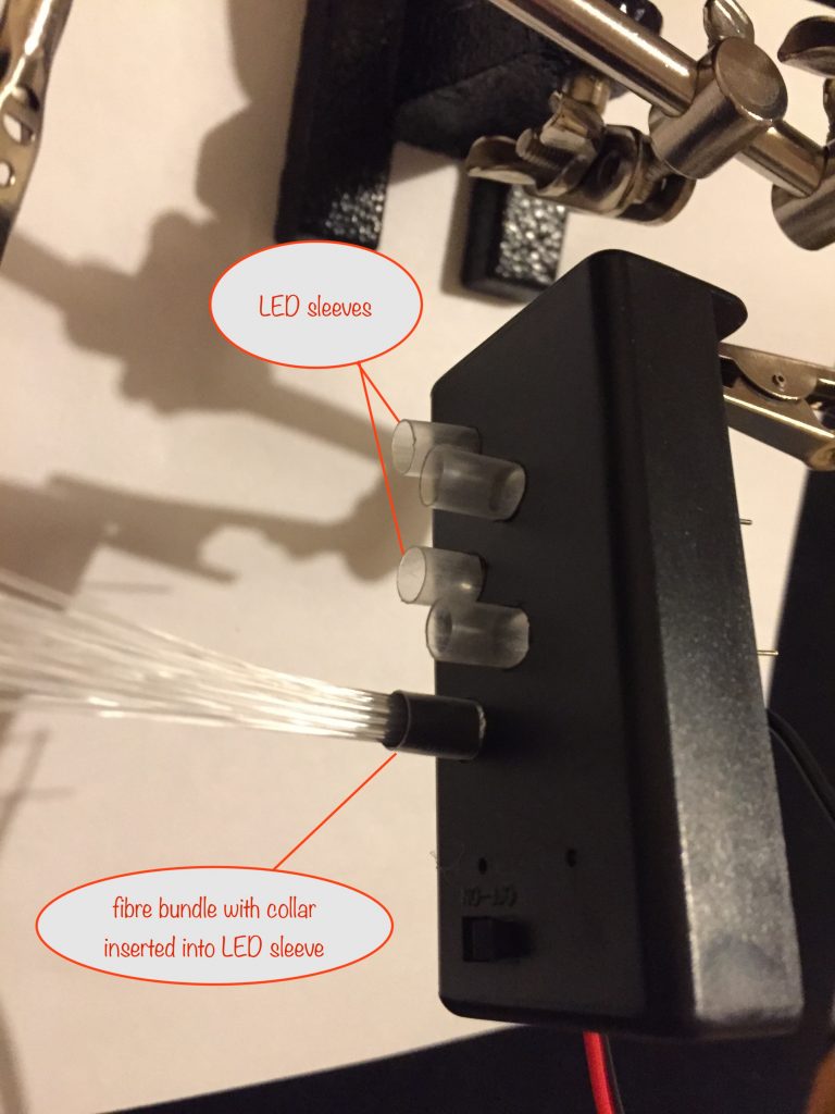
- fit the stripboard in place with the LED sleeves poking though the fibre bundle holes and with the tops of the LEDs poking out a little above the battery box plastic
- use some hot glue to hold the stripboard in place. Some anchoring each corner to the battery box should do the job
- knot the power-in lead for strain relief, protecting their soldered joints
- solder the power-in negative lead to the battery box switch
Placing and UV-gluing the fibre bundles
Put the base of the battery box into place to make these steps easier. One by one, do each fibre bundle in turn.
Placing the fibre bundle and adding the UV glue
- make sure the LED sleeve is vertical
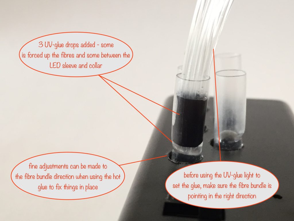
- put two or three drops of UV-glue into the sleeve so the top of the glue is around 2mm above the top of the LED
- insert the fibre bundle and its collar fully into the LED sleeve so the fibres touch the top of the LED. Make sure the fibres curve in the direction you want, probably angled slightly outwards for the outside ones and straight forward for the ones closer to the middle.
- some of the UV-glue will be forced up into the fibres and some will be forced between the collar and the LED sleeve
Setting the UV glue and heat-shrinking the sleeve
- now you can shine the UV glue-setting light all the way around to solidify the glue
(it won’t form a perfect hold but it’s half the battle). Do it for a good 30 seconds to be sure it’s done its job. - Next, take your soldering iron and very carefully use it to shrink the LED sleeve onto the collar (the collar will also shrink a little as the heat transfers through to it). Don’t touch the fibres – even a little bit or you’ll likely warp them
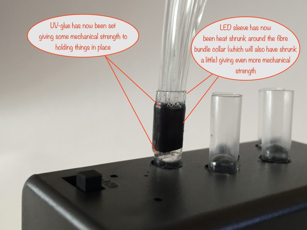
The UV-glue together with the shrunk sleeving will make things robust enough now to withstand a little punishment. Full strength won’t be achieved until later when you encase everything (up to where the fibres enter the top of the colllar) in hot glue.
Hot gluing the fibre bundles
This serves three purposes:
- allowing you to make fine adjustments to the fibre bundle directions
- preventing light leakage where the LEDs leave the battery box
- giving final mechanical strength to the fibre bundles
Final fibre bundle adjustments
Before encasing the fibre bundles completely, you may want to make some fine adjustments to the direction each bundle points in so that you get the display you want.
To do this, anchor each fibre bundle around its base with hot glue and make the adjustment. You’ll need to hold things still while the glue is cooling down to ‘lock in’ the new position.
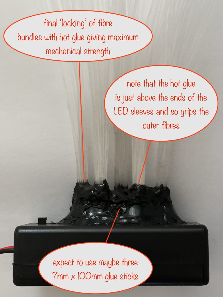
Encasing the fibre bundles
When you’re happy with the positions, encase them all in hot glue up to and just over the tops of the collars. This will give the final strength to the whole arrangement and make sure your fibres stay in place.
Just be careful that the tip of your glue gun doesn’t come into contact with the fibres for fear of warping them.
It all gets a bit messy and you’ll end up using two or three glue sticks – but that’s ok because the end result is worth it.
Splaying the fibres
This is optional but if you want to splay out the fibres a little, then here’s a neat way of doing it:
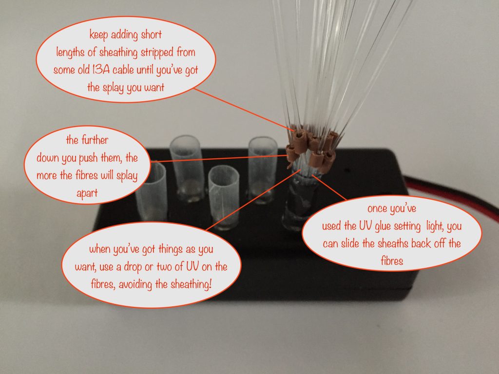
Take some old mains / 13 amp electricity cable and strip off the plastic sheathing in 3 or 4mm lengths. The plastic sheath holes should be wide enough to fit over a fibre.
Slide those sheaths over some of the fibres and push down towards the base. Keep doing this with more fibres until you have the amount of splay you’re after.
Finally, add some UV glue to the base of the fibres and set it with the UV light. You can then remove the lengths of sheathing and use them to do the next bundle of fibres.
Finishing off
As things are so far, the battery box will overbalance. There’s a couple of things you can do to prevent this. You can:
- use Blu Tack (or equivalent) to stick it where you want it
- make front feet using hot glue
Other projects in the Nifty Hobby Projects for LEDs and Solar series (so far, more to come very soon):
- Flasher Memory Aid
- Dark-activated Switch
- 5 LED String
- Mini Sparkles Colour-changing LED Fibre Optic String
- Solar Lithium Ion Battery Charger
- Solar NiMH Battery Charger for 2 AAA batteries
- Solar NiMH Battery Charger for 2 AA batteries
- Solar NiMH Battery Charger for 6 AA batteries
- Timer-delay Off Switch
- 4-LED Porch Light
- 10-LED Bedside lamp
- Mini Camping / Bedtime Reading Lamp
- Main page with links to where to buy stuff