Finally, the LM317LZG voltage regulators arrived so I was able to finish the build and tutorial.
Finally, the LM317LZG voltage regulators arrived so I was able to finish the build and tutorial.
The one thing holding me up on doing the tutorials for the rechargeable NiMH circuits is the global semiconductor shortage.
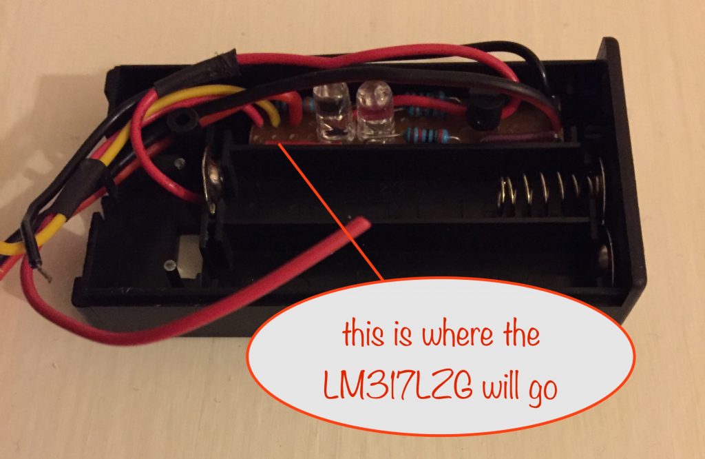
The AAA recharger version doesn’t have much room and so needs to use the TO-92 version of the LM317 voltage regulator. As you can see, there’s not enough room for the larger TO-220 package
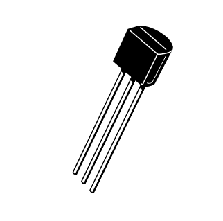
Here’s what the TO-92 package looks like:
I ordered a bunch from Farnell and was initially given a delivery date of Dec 17th (2021) but, as the day approached, it shifted to Dec 26th… then Jan 7th, then Jan 21st, then Jan 31st and it’s now at Feb 7th.
So I’ve ordered some from ebay and when they arrive (tomorrow?) I’ll cancel the order with Farnell.
I’m not happy about the delay but I have managed to make progress with other projects while I’ve been waiting.
The prototype solar tracker is now in its final version and I’ve been playing with some 1W warm white LEDs to use with the batteries it’ll charge. That way I can use them in place of some of my mains-powered lighting, helping a little to reduce my carbon footprint – and save money on electricity bills at the same time. Nice!
Watch for blog posts about them both.
I’ve been working on a project (coming very soon) in my solar / renewables series that lets you charge NiMH rechargable batteries.
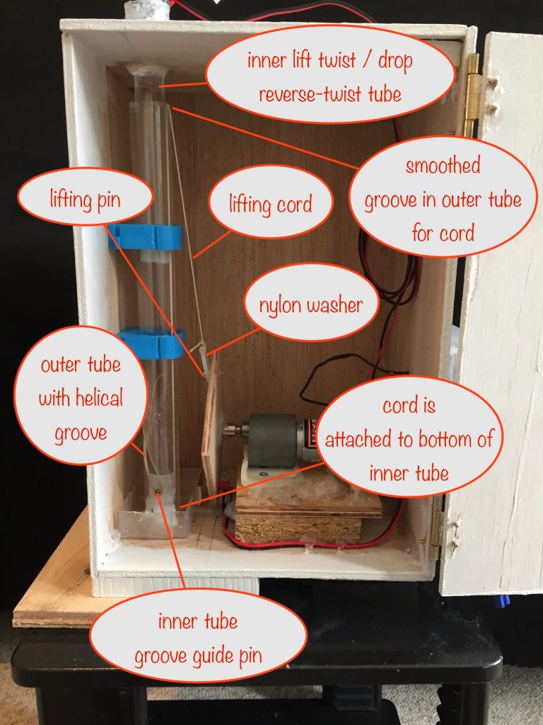
What a journey! Here’s a prototype I built to help me visualise the way forward:
The challenges to overcome are that the batteries come in two different sizes – the smaller AAA and the larger AA ones. More than that, they come in lots of different capacities and each capacity has to be charged at a different rate.
Another complication is that the solar panel needed depends both on the number of batteries to be charged and the charging current – Ohm’s law tells us that the solar panel power needed is the total battery voltage x the charging current.
Coming up with the most practical combination for the project with all those variables proved to be a real mind bender.
In the end, after much checking of physical sizes and layouts of the charging circuit compared with the available space in AA and especially AAA battery boxes, I decided on two projects – a solar charger for:
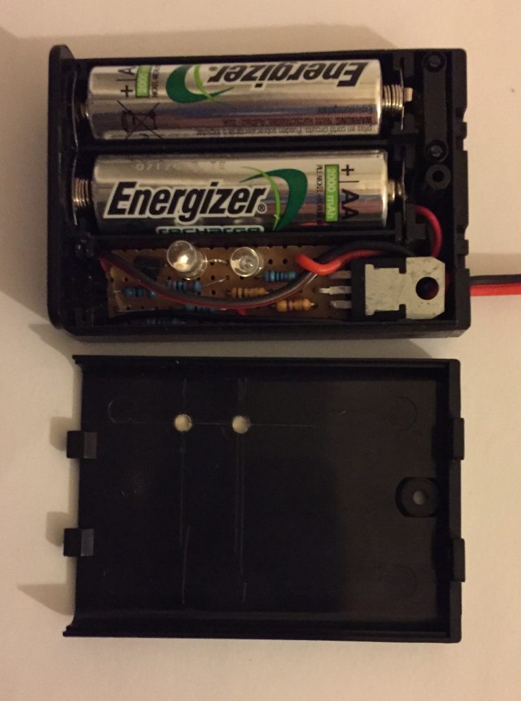
Here’s a comparison of the size of the lower power version (TO-92 package) on the right, with the higher power one (TO-220 package) on the left.
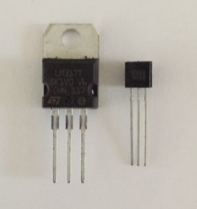
With so little space to play with in the AAA battery case, you can see why it’s circuit needs to use the lower power version!
To help get my head around things, here’s the table I put together covering many of the commonly available battery capacities, the resistors needed to set the manufacturer-recommended C/10 safe charging currents for them and the resulting solar panel wattages:
| Battery Capacity (mAh) | R1 value (Ω) | C/10 charging current (mA) | 2 Battery 6V Solar Panel | 6 Battery 12V Solar Panel |
| 500 | 15 + 10 | 50 | 0.5 Watt | 1 Watt |
| 700 | 18 | 69 | 0.5 Watt | 1 Watt |
| 800 | 10 + 5.6 | 80 | 0.5 Watt | 1 Watt |
| 900 | 10 + 3.9 | 90 | 0.6 Watt | 1.5 Watt |
| 1000 | 10 + 2.7 | 98 | 0.6 Watt | 1.5 Watt |
| 1300 | 8.2 + 1.5 | 129 | 0.9 Watt | 1.8 Watt |
| 2000 | 4.7 + 1.8 | 192 | 1.25 Watt | 2.5 Watt |
| 2300 | 3.3 + 2.2 | 227 | 1.5 Watt | 3 Watt |
| 2400 | 2.7 + 2.7 | 231 | 1.5 Watt | 3 Watt |
| 2500 | 3.3 + 1.8 | 245 | 1.5 Watt | 3 Watt |
| 2800 | 3.3 + 1.2 | 278 | 2 Watt | 4 Watt |
| 2900 | 2.2 + 2.2 | 284 | 2 Watt | 4 Watt |
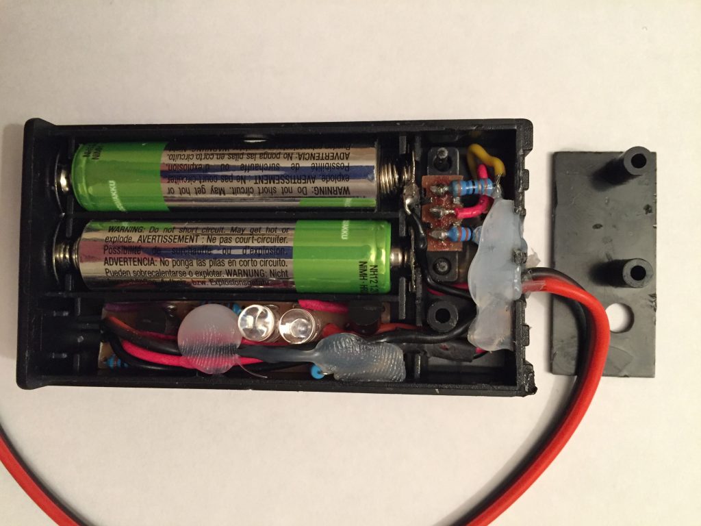
I’m sure I’m not the first but I’ve not seen anyone else doing this. Have a look at the photo at the top and you’ll see two holes in the battery box lid to let the LEDs show through.
If you look closely, you might notice that they’ve been filled with uv glue. That way, the LEDs can still shine through but water / dust won’t get into the box.
It’s simple to do – just drill a couple of holes and then stick some sticky tape on the underneath. You can now fill the holes with uv glue and it won’t run away while you set it. Once set, just peel away the sticky tape.
Nice!
by Mark Ridley, our resident electronics hobbyist
After a few months, the acrylic tubes shattered in high winds – they couldn’t take the repeated battering. I’ve now replaced them with aluminium tubes and it’s working well.
If you saw my previous post, you’ll notice that I’ve reduced the size of the solar panel mount. The end result is that the mount, including solar panels, now weighs just under 800 grams (22 oz) – down from around 1kg.
Watch it in action:
During the day, the secondary solar panel drives the motor when unshaded by the main solar panel (and the sun is shining).
The end result is that the main solar panel is once again pointing at the sun and this continues throughout the day as long as there is enough sunshine.
This is the really cool part! At dusk the main solar panel stops providing power to the battery charger module. This causes its output circuit to switch on power, for example, to an attached garden LED string.
That’s its normal function – and we make use of it to reset the solar panels as described below.
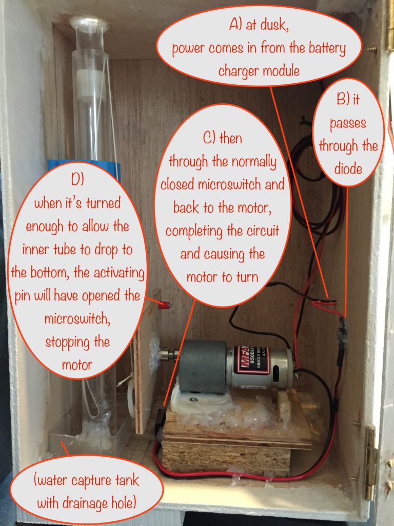
I’ve also included a water capture ‘tank’ with a drainage hole. This makes sure that any rainwater running down the inner tube from the outside gets returned to the outside.
I used the tip of a plastic nozzle I’d kept in my box of bits (from an emptied tube of silicone sealant) to line and poke out the bottom of the drainage hole. That way the water is guided away from the bottom of the box.
Hopefully it’s wide enough to do as needed without being so wide that it makes a cozy home for any little beasties!
NB On an overcast day, it doesn’t really matter in which direction the solar panel points because scattered light comes in pretty much equally from all directions. If they haven’t moved from their morning position nothing happens when darkness falls because the micro switch is still activated (ie open). If they have, the motor will be powered by the battery to reset them back to the morning position as described above.
Well, it’s been a fun project getting to this stage, very apposite given that COP26 in Glasgow has just finished.
I hope I’ve inspired you to start using renewable energy for your own projects. Please let me know in the comments 😎
One last idea – instead of just charging a battery with a solar panel, you could also fix some form of mirrored surfaces to the mount to direct sunlight into areas of your garden that don’t get much sunshine.
I’ve been working out how to mount the solar panels onto the rising and falling tube. Not being very mechanically minded, it’s been a bit of a struggle – hot glue to the rescue!
Rather than work directly with the acrylic tube on my (partially) working prototype, I found another plastic tube that fits nicely on top of it and am working with that.
Here’s a side view showing details of how I’ve constructed it.
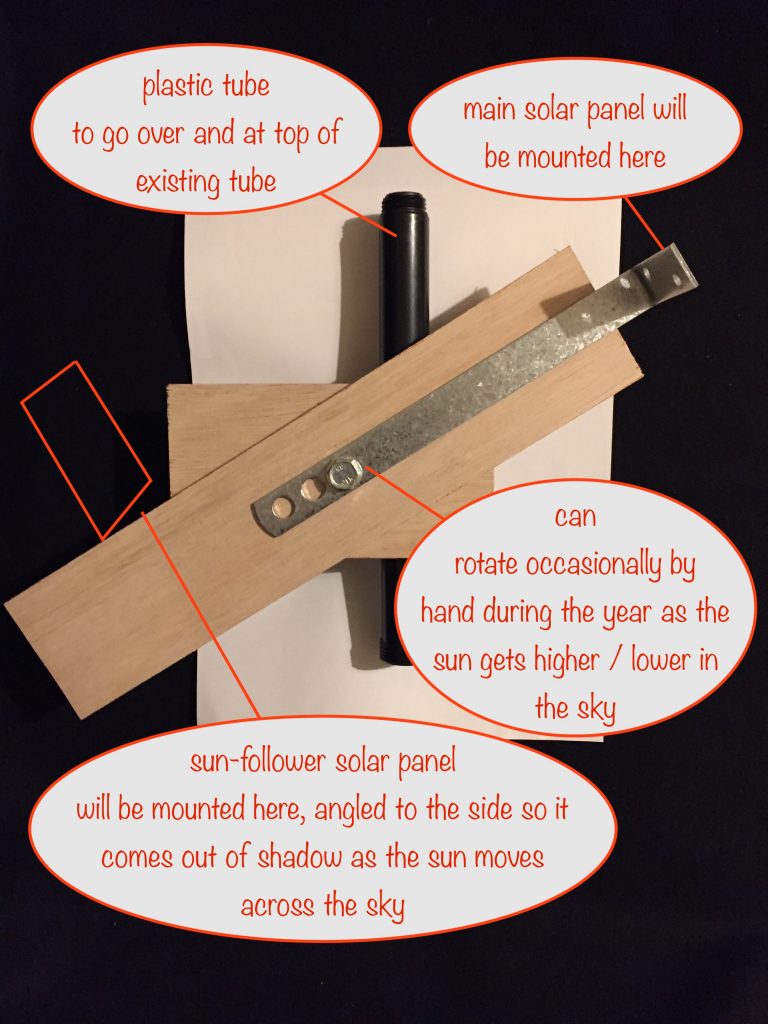
I’ve still to get another angle bracket for the other side so you’ll see it’s missing in this top view of the assembly:
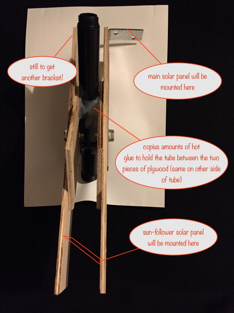
With the sun-follower solar panel angled as shown, when the sun moves far enough across the sky so that it’s no longer in the shade of the main solar panel, power will be delivered to the motor.
As the motor rotates, it lifts and turns the central tube. This will put the sun-follower solar panel back in the shade of the main solar panel, which is now pointing directly at the sun. So the motor no longer gets power and rotation stops until the sun moves far enough across the sky again.
When dusk arrives, the main solar panel stops producing power. When this happens, the battery charging circuit switches off and the battery gets connected to the output.
Whatever else the output may be connected to (string of garden LEDs etc) it will start supplying power to the motor. This will rotate the whole mechanism until the tube reaches the bottom of its travel and so resets the solar panel to the dawn position.
At the same time, as it reaches the bottom of its travel a normally closed reed switch is opened by a strategically placed magnet, turning off power to the motor.
Note that I’ve called the sun-follower solar panel “secondary solar panels” in the sketch.