this is another mix ‘n match module in the Nifty Hobby Projects for LEDs and Solar series – written by team-member Mark Ridley
Edit Dec 26th, 2021: I’ve updated the circuit diagram to include a fix to the problem where sometimes it wasn’t switching on at the beginning when power was applied. R1 has been changed from 1MΩ to 100kΩ and a 0.1μF ceramic capacitor (C2 in the schematic) added between pin 12 of the CD4060 and the positive rail.
The main purpose of this module is for you to use it with the Solar Lithium Ion Battery Charger module to preserve your battery’s juice.
I’ve designed it to do this by switching off the load it’s powering after one of two preset intervals; 5 hours and 8 hours (both approximate).
You could use it for other things – one of the reasons I’ve made it modular. Just give it power and use its power-out leads to power whatever you want. It can handle up to 20V and a couple of amps.
The interval you want to be used is set when you place or remove a magnet that closes or opens a reed switch, respectively. With the magnet you’ll get a 5 hour delay and without, it’s 8 hours (or you can swap this around – see below in the reed switch part of the build).
If for some reason you want different timings, see the timing resistor calculations at the end, otherwise ignore them 😎
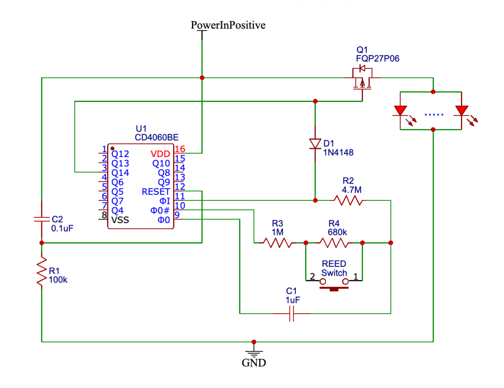
Schematic of Timer-delay Off Switch
How it works
The chip is a CD4060 counter with various outputs labelled Q1 to Q13. The resistor / capacitor network R3, R4 and C1 set the frequency of a pulse that gets counted.
C2 and R1 together make sure that when power is applied, the CD4060 gets correctly reset so it starts counting from zero.
The chip has a number of outputs (labelled Q1 – Q14) that start off at a low voltage and go to a high voltage when the counts that they’re designed for have been reached.
The one we’re interested in is Q14, the one that goes high after 8192 pulses. With the resistor / capacitor network having the values shown, this happens after 5 hours (reed switch closed) or 8 hours (reed switch open).
When it goes high, the 1N4148 diode causes the pulses to stop by taking pin 11 of the chip high.
Without the magnet, both R3 and R4 are used in setting the pulse freqency. With the magnet, the reed switch closes, shorting out R4 so that only R3 features in setting its frequency.
Timings aren’t very precise because of component tolerances but they’re close enough for the purposes of this module.
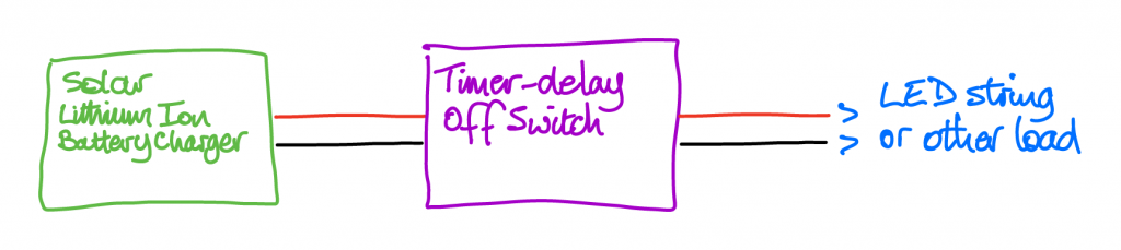
When used with a LED string and the Solar Lithium Ion Battery Charger, which provides power at its output when dusk falls, this is how it goes:
- during the day the battery is charging, no power goes to the Timer-delay Off Switch, LED String is off
- dusk falls and the solar panel stops charging the battery and starts giving power to the Timer-delay Off Switch
- the Timer-delay Off Switch starts counting the pulses it’s now started to generate. While it’s doing that, the gate of the P-Channel MOSFET is held low by the output of Q14 (the one whose output stays at a low voltage until it’s counted 8192 pulses).
When the MOSFET’s gate is low, it’s switched on, causing it to supply power to the connected LED string - when 8192 pulses have been counted, Q14 goes high, taking the MOSFET gate high. When this happens, the MOSFET switches off, removing power to the LED string so it switches off as well
- when dawn next arrives, the Solar panel starts charging the Lithium Ion battery and this stops the charger module supplying power at its output. Without this power, the Timer-delay Off Switch is powered down, resetting its counters ready for its next switch-on at dusk later in the day.
- The whole process repeats each day, eeking out the battery’s juice.
Preparation
Tools etc. you’ll need:
- 18 Watt soldering iron, 25 Watts at a push
- Desoldering pump / solder wick – in case of mistakes!
- “Helping Hand”
 – invaluable aid while soldering or gluing
 - Wire strippers covering 26 to 16 AWG
- Side cutters
- Small snipe-nose / needle-nose pliers
- Set of watchmaker-style screwdrivers for adjusting the trim pot – also for general poking, prodding and levering
- Glue gun for sealing the enclosure to keep out the rain and for protecting the magnet with a covering of glue
- Small hobbyist drill with a 2mm and 3mm drill bit (plus larger ones if your power leads need it)
- Continuity tester for checking the magnet operates the reed switch. Challenge – make your own with a 9V battery, an LED and a 330Ω-ish current-limiting resistor
Components / parts list
See the main page (opens in new tab) for links to where you can buy these.
NB All resistors are ¼Watt. 1% or 5% tolerance are good, 10% at a push.
- 1x FQP27P06 P-channel MOSFET (TO-220 package)
- 1 x 1N4148 diode
- for testing the switch:
- a charged 3.7V Lithium Ion battery (or suitable alternative)
- LED with a 220Ω (or thereabouts) current-limiting resistor soldered to one of the legs
- 1 x 680kΩ resistor
- 1 x 100kΩ resistor
- 1 x 1MΩ resistor
- 1 x 4.7MΩ resistor
- 1 x 0.1μF ceramic capacitor
- 1 x 1μF ceramic capacitor
- 1 x Stripboard, 12 columns by 12 rows
- 1 x Reed switch (normally open)
- 1 x Neodymium (or suitable alternative) magnet for activating the reed switch when needed. I use an 8mm x 3mm one. It must be weatherproof as it’ll be left attached to the enclosure housing the timer-delay off switch when in use. See later for weatherproofing the magnet.
- 1 x weatherproof enclosure. A Business Card plastic storage box you can get from ebay is ideal for this – or why not use a plastic box that curries get delivered in? Alternatively, you could incorporate it as part of your Solar Lithium Ion Battery Charger, as that’s its main use. See later for more on this.
- 1 x Power input lead – twin flexible, multi-strand 20 swg is good
- 1 x Power output lead – twin flexible, multi-strand 20 swg is good
- Various short lengths of wire for making stripboard connections
- your choice of connectors, female for power in and male for power out. This is so you can connect up to other mix ‘n match modules. I’m using EC5s
 because I had a bunch to hand, you may prefer the EC3s or another robust, weatherproof-able connector
On with the build…
The build
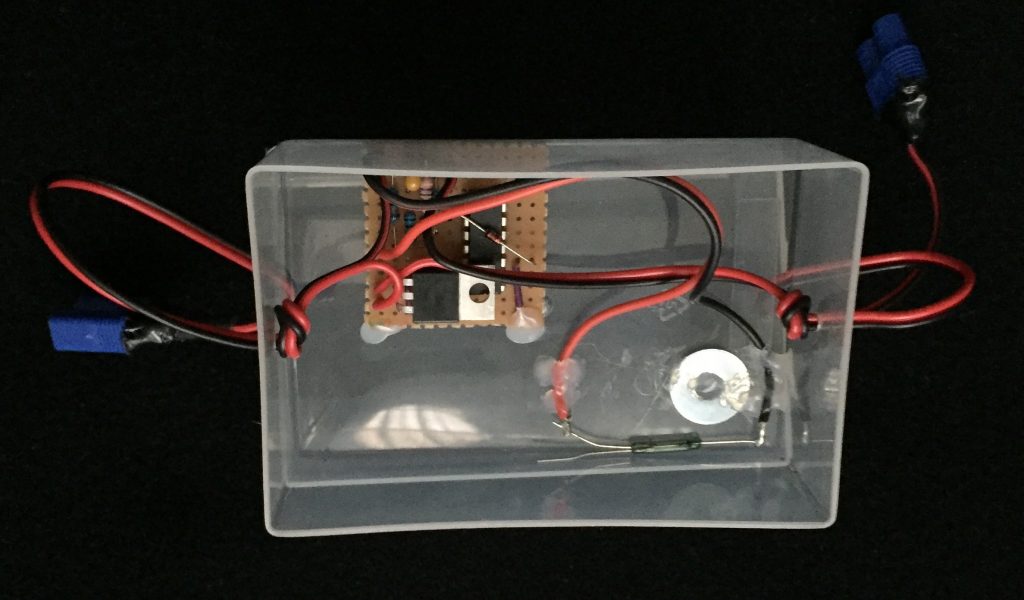
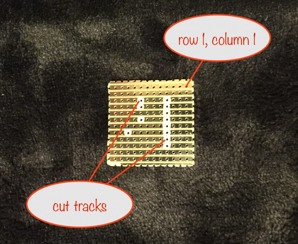
Prepare the stripboard
The stripboard is 12 columns by 12 rows, so cut along the 13th row and column. A great way to cut stripboard is shown in this YouTube video
Next, use one of your drill bits to manually cut the tracks as shown.
Note that when it’s flipped over like this, row 1, column 1 is now on the right hand side.
Stripboard layout
Take care when handling the CD4060 chip as it’s sensitive to and can be damaged by static electricity. Touch a large metallic object such as a radiator before handling. This will discharge any static build-up in your body.
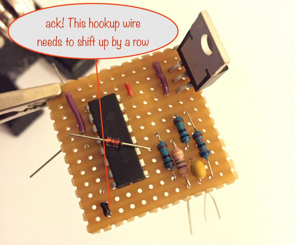
You can now start to add your components to the stripboard.

(click to open a larger image in a new tab)
This is what it should look like with all components placed. Note that I’ve had to bend the MOSFET up again for the photo. I like it bent parallel to the board (leaving a little space betwen its heatsink and the counter chip) so it takes up less vertical space.
(Edit Dec 26th 2021: This hasn’t been updated with the changes mentioned at the top)
I’ve flipped the stripboard over so you can see the other side. Note how I’ve bent the legs of the various components to ‘lock’ everything in place (only pins 8 and 16 on the counter chip).
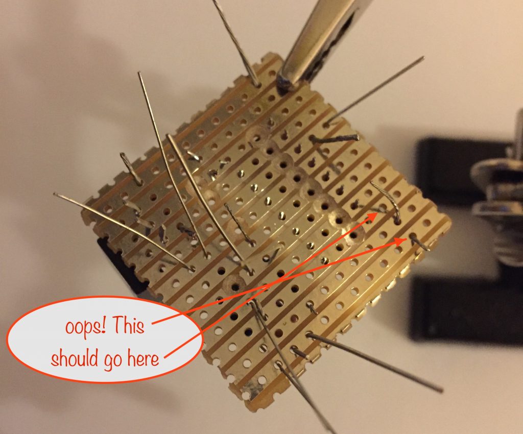
My oopsie demonstrates how important it is to do a complete visual check before soldering (or photographing, hehe!) As it happens, it was only when I was soldering the power and reed switch wires that I noticed, so it was too late to redo the photos.
Preparing the box to put it in
Start off by drilling holes in either end of the box to take the power-in and power-out leads.
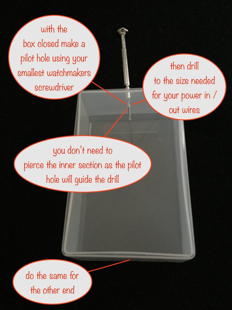
Use your smallest flat-bladed watchmakers screwdriver to make a pilot hole. Even though the photo shows both sections pierced (I was eager!), you only need to pierce the outer wall.
Next, drill through both walls and go up in drill bit sizes to enlarge the hole to the size needed to take your leads. 3mm was good for mine.
Now do the other end.
Be careful in a moment that you don’t mix up the ends or the holes won’t line up when you’ve threaded the leads through and go to close the box!
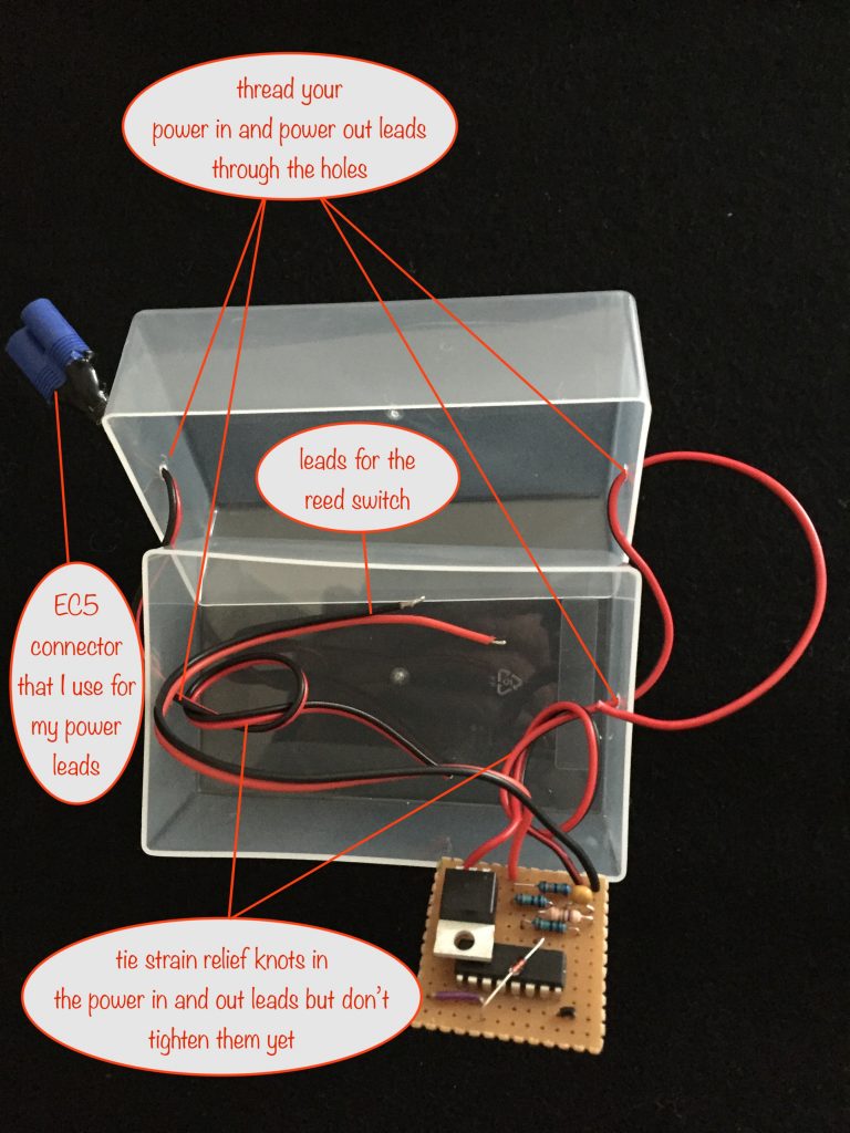
Note the strain relief knots are loose for now. You’ll tighten them later, just before placing the reed switch and steel washer.
Positioning the washer
The purpose of the washer is to:
- give the magnet something to cling to…
- ..while still allowing it to activate the reed switch
Don’t do as I originally did and centre the washer on the reed switch – it won’t work in that position! Instead mount it beside the reed switch as shown in the photo, below.
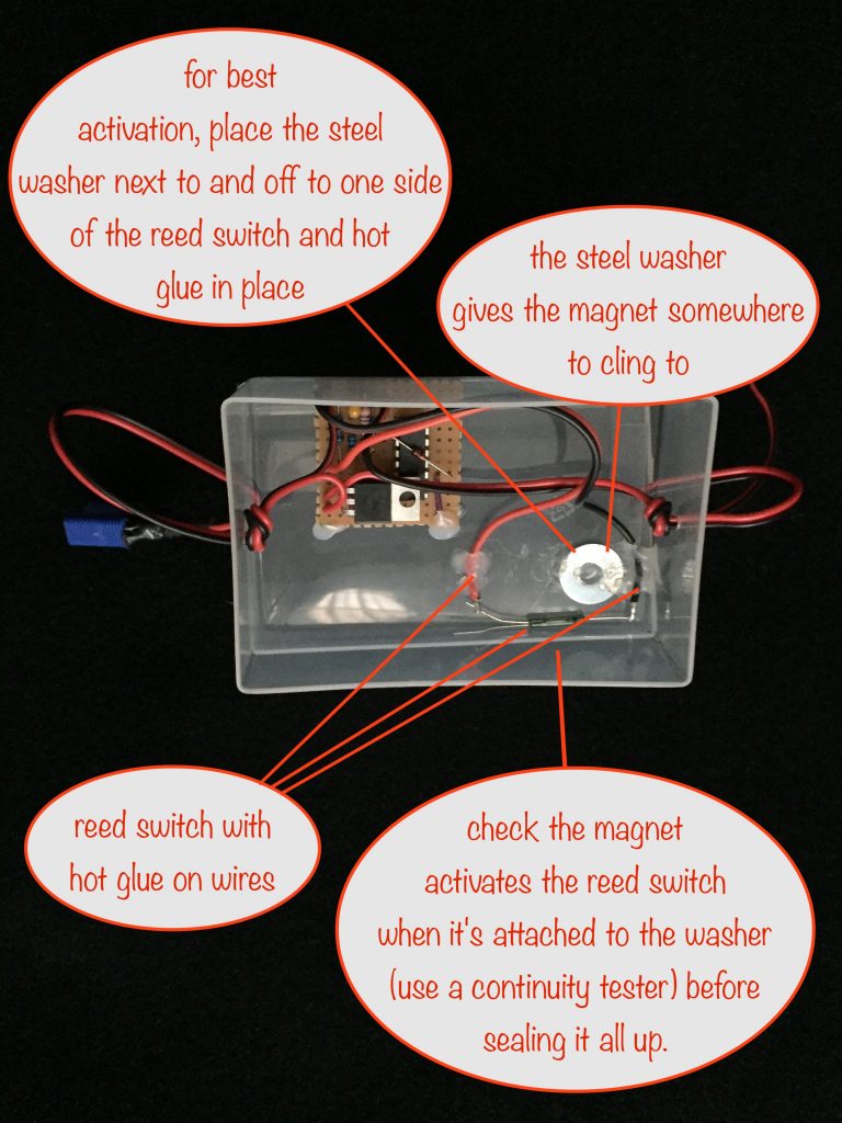
I’ve chosen an easy-to-source reed switch and it has two switch positions, normally open and normally closed. The normally open one is the shorter of the two legs on the left in the photo. I’ve carefully bent the normally closed one down and out of the way.
If you’d rather have 5 hours without the magnet and 8 hours with, then instead of soldering to the normally open connector, solder to the normally closed one instead.
I’ve mounted the reed switch and washer in the bottom of the box here (cause I’m stoopid 😜) You may prefer to mount them in the top. It’s a bit more fiddly but at least then the magnet gets put on the top. Much easier to use!
Before hot-gluing the steel washer in place, tack it down first and then use your continuity tester (remember, you can make one out of a 9v battery, an LED and a 330Ω current-limiting resistor). You want to make sure that the reed switch activates, wherever you place the magnet on the washer.
Once you’ve checked that, you can properly hot glue the washer in place, tighten the strain relief knots and fit the box together.
Weatherproofing the box and leads
Before weatherproofing – by sealing it up using hot glue around the edges and the lead holes – it’s a good idea to give it a test indoors if you can. It’s easier indoors otherwise you have to wait for dusk, then stay up until 3am for the 8 hour test! Besides, you can be sure it won’t rain indoors 😄
I found out that it’s important to use adhesive-lined heat shrink on the leads at the point where they enter the box. The reason is because hot glue doesn’t always form a perfect seal around the leads, especially with twin leads in a figure of eight and some rainwater can get into the box via the groove between them.
So use that heat shrink where the leads enter the box before applying the hot glue.
Weatherproofing the magnet
If you don’t do this, the magnet will rust. So use hot glue to cover the magnet and at the same time make a small grip for it as shown.
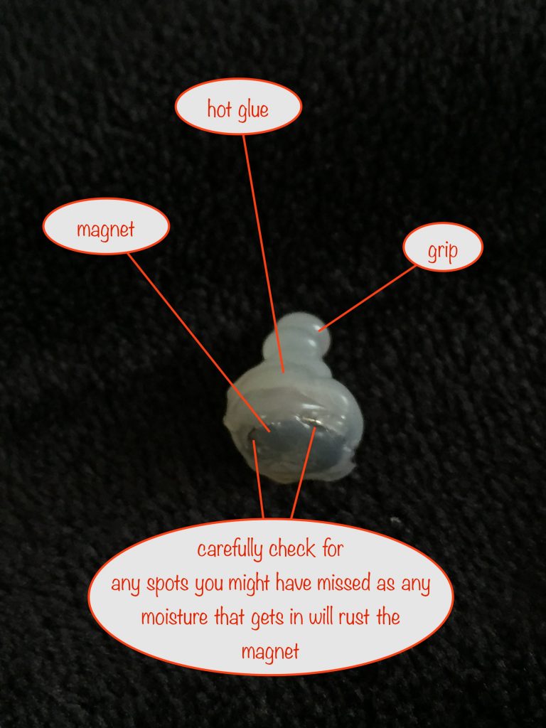
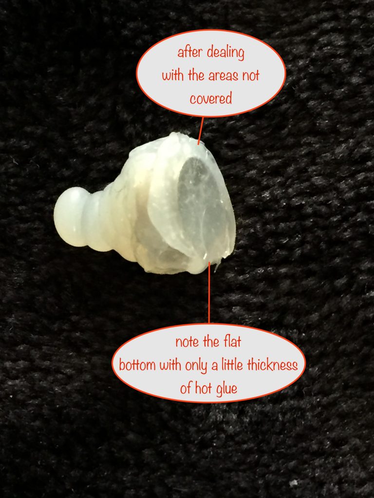
Once you’ve checked that there are no spots where moisture can get in. Once you’ve done that you can warm up the bottom to slightly melt the hot glue and then press the magnet against a cold surface to give a nice flat bottom.
Don’t press too hard, just hard enough so you’ve got a thinnish layer of glue at the base.
If it’s too thick, it might hinder the magnet from being able to activate the reed switch. If it’s too thin, it might get pierced in use and then let moisture in.
Options
Mounting your circuit in the Solar Lithium Ion Battery Charger module
If you don’t mind the Timer-delay Off Switch being a permanent addition to your charger module, just cut another flap in the base and mount the completed circuit, washer and reed switch on it.
Before you seal it up, make sure that the magnet actually operates the reed switch! If it doesn’t, make sure the washer is attracted by the magnet and make sure it’s placed like shown in the photo above.
Changing the 5 hour / 8 hour timings
If for some reason you need to change the time delay to switch-off, here’s the info you need. If not, ignore this bit 🤪
The data sheet for the CD4060 tells us the frequency of the pulse it generates is given by this formula:
Frequency f (Hz) = 1 / ( 2.2 x C1 x (R3 + R4)
Note that R2 needs to be somewhere between 2 and 10 times the value of (R3+R4).
Q14 goes high after 8192 pulses, so the time it takes in seconds is 8192 divided by the frequency. For the sake of argument, let’s say you want a delay before switch-off of 8½ hours (no magnet) and 4½ hours with the magnet:
8½ hours is 30600 seconds, so
30600 = 8192 / (1/(2.2 x 0.000001 x (R3+R4))), ⇒
30600 x 1/(2.2 x 0.000001 x (R3+R4)) = 8192 , ⇒
1/(2.2 x 0.000001 x (R3+R4)) = 8192/30600 , ⇒
1 = (2.2 x 0.000001 x (R3+R4)) x 8192/30600 , ⇒
1/(8192/30600) = 2.2 x 0.000001 x (R3+R4), ⇒
3.735352 = 0.0000022 x (R3+R4), ⇒
3.735352/0.0000022 = R3+R4, ⇒
1697887Ω = R3+R4
4½ hours is 16200 seconds and repeating the calculation (R4 will be 0, shorted out by the reed switch when it’s activated by the magnet) gives:
1/(8192/16200) = 2.2 x 0.000001 x (R3+0), ⇒
1.997754 = 0.0000022 x R3, ⇒
1.997754/0.0000022 = R3, ⇒
898881Ω = R3
If that’s R3, then R4 is 1697887Ω – 898881Ω = 799005Ω
Rounding the values gives R3 = 900kΩ (closest standard value is 910kΩ from the 5% range), R4 = 800kΩ (closest standard value is 810kΩ from the 5% range)
Other projects in the Nifty Hobby Projects for LEDs and Solar series:
- Flasher Memory Aid
- Dark-activated Switch
- 5 LED String
- Fibre Optic Display
- Mini Sparkles Colour-changing LED Fibre Optic String
- Solar Lithium Ion Battery Charger
- Solar NiMH Battery Charger for 2 AAA batteries
- Solar NiMH Battery Charger for 2 AA batteries
- Solar NiMH Battery Charger for 6 AA batteries
- 4-LED Porch Light
- 10-LED Bedside lamp
- Mini Camping / Bedtime Reading Lamp
- Main page with links to where to buy stuff