this solar panel powered battery charger is another module in the Nifty Hobby Projects for LEDs and Solar series
Written by team-member Mark Ridley
This tutorial shows you how to build a charger for 2 AA NiMH batteries. You decide on which two battery capacities you want to be able to charge with it and there’s a switch to let you flip between them.
- to build one for 2 AAA batteries, see this project
- to charge 6 AA batteries at a time, see this project
Set up your circuit for the 2 lowest capacity batteries you have and they’ll take one sunny day (10 hours) to charge. Then any higher capacity batteries can still be charged without harm – they’ll just take longer.
For example, I’ve set mine up to charge 500mAh or 1300mAh batteries. I’ve got some 2000mAh batteries as well and they’ll happily charge in around a day and a half on the 1300mAh setting.
Description
Using renewable energy is really important as we try and counter the effects of global warming and this a fantastic and practical project for it – every household needs at least one!
If your kids (or you are a kid) have already shown interest in saving the planet, this could be a great project for them to get involved with. Who knows where it might lead?
On a more practical note, using a solar panel to charge your NiMH AA batteries means you’ll always have some fully charged and ready to be used. Perfect for TV remotes, toys and other battery-operated goodies.
Features of Module
Here’s the main things your charger will do:
- fully charge your batteries in one sunny day (10 hours)
- battery box switch allows 2 different battery capacities to be charged
- you choose the capacities you want charged – you can charge higher capacity batteries than your chosen ones but they’ll take longer than the 10 sunny hours
- green LED indicates when enough charging volts from the solar panel are present
- red LED indicates when batteries are fully charged (and charging volts are present)
- manufacturers’ recommended C/10 charging used so leaving them on charge once they’re fully charged won’t cause any harm
Circuit Diagram

(click to see larger in new tab)
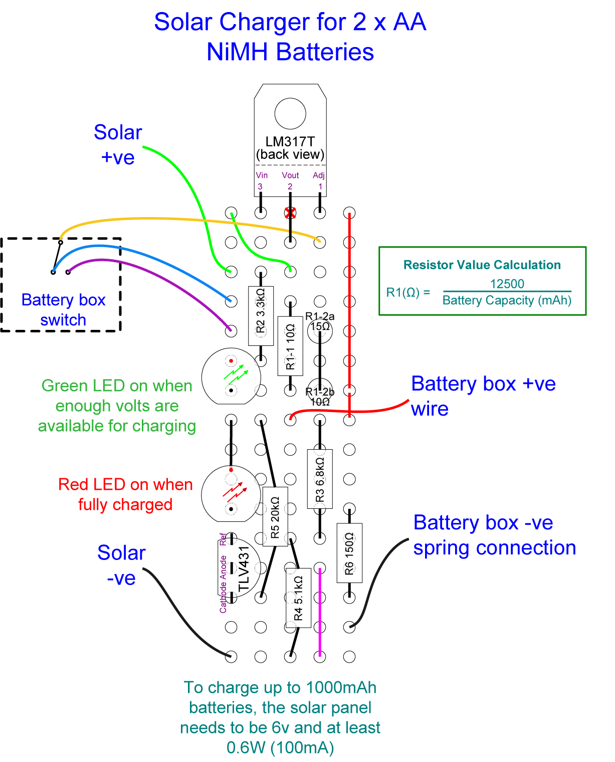
With the values shown for R1 in the schematic you’ll be able to charge either 2 x 1300mAh (R1-1) or 2 x 500mAh (R1-2) batteries, as selected by the battery box switch.
As there isn’t room for a heat sink for the LM317T, the highest capacity batteries you’ll be able to charge is maybe 1800mAh.
Circuit notes
The circuit is split into two parts:
- a constant current section for charging the batteries
- a voltage monitor section for indicating when the batteries are charged
Contant current section
This gets its power from the attached solar panel when the sun is shining and uses an LM317T chip to convert the power to a constant current for charging the batteries.
When there’s enough power available from the solar panel to put charge into the batteries, the green LED will be on. If it’s very dim, then you’ll only be getting maybe 10 or 20 milliamps into your batteries but at normal brightness, all is good.
The values of R1 used in the schematic limit the current to either 125mA (R1-1) or 50mA (R1-2). That’s just under the highest recommended charging current for 1300mAh and 500mAh NiMH batteries (C/10).
Voltage monitor section
This section uses a TLV431 adjustable shunt regulator chip to turn on the red LED when the voltage set by the values for R3 and R4 is reached. With the values given in the schematic, the red LED will switch on when the battery voltage reaches 2.89V.
A fully-charged 1.2V NiMH battery is 1.5V, so 2 in series will be 3V. This means that when the red LED comes on, they’ll be at maybe 96% or so of full charge.
Note that leaving them charging once they’ve reached full charge won’t cause any damage because the current is limited to C/10, as recommended by battery manufacturers.
About the solar panel
As this charger is for 2 batteries, the voltage of the solar panel you’ll need is 6V. The solar panel power (watts) you need depends on the highest capacity of the batteries you want to charge. See the table at the end for details of the required solar panel wattage for common NiMH battery capacities.
NB If your solar panel includes a diode, it’s not needed so you can short it out. That way the panel’s full voltage will be delivered to the circuit and give the LM317T the headroom it needs.
Components list:
- LM317T Adjustable Regulator for the constant current source
- TLV431 Shunt Regulator for the charge completion detection
- 1 x Green LED
- 1 x Red LED
- R1-1: Given here as 10Ω for a 1300mAh battery capacity
- R1-2: Given here as 25Ω for a 500mAh battery capacity
(There isn’t a commonly available 25Ω resistor, so I’ve used a 10Ω and a 15Ω resistor in series as you’ll see in the stripboard layout, below) - R2: 3.3kΩ current limiter for green LED
- R3: 6.8kΩ
- R4: 5.1kΩ
- R5: 20kΩ
- R6: 150Ω current limiter for red LED
- hookup wire in various colours
Tools etc. you’ll need:
- 18 Watt soldering iron, 25 Watts at a push
- “Helping Hand”
 – invaluable aid while soldering or gluing
 - Wire strippers covering 26 to 16 AWG
- Side cutters
- Small snipe-nose / needle-nose pliers
- Glue gun for insulating components and wires and fixing everything in place
- UV glue for letting LED light shine through the battery box
- Small hobbyist drill with a 2mm, 3mm, 4mm and 5mm drill bit
Preparing the battery holder
The circuit fits neatly into one battery slot in a standard AA battery box so for this setup you’ll need a 3 AA battery box.
Preparing the battery box
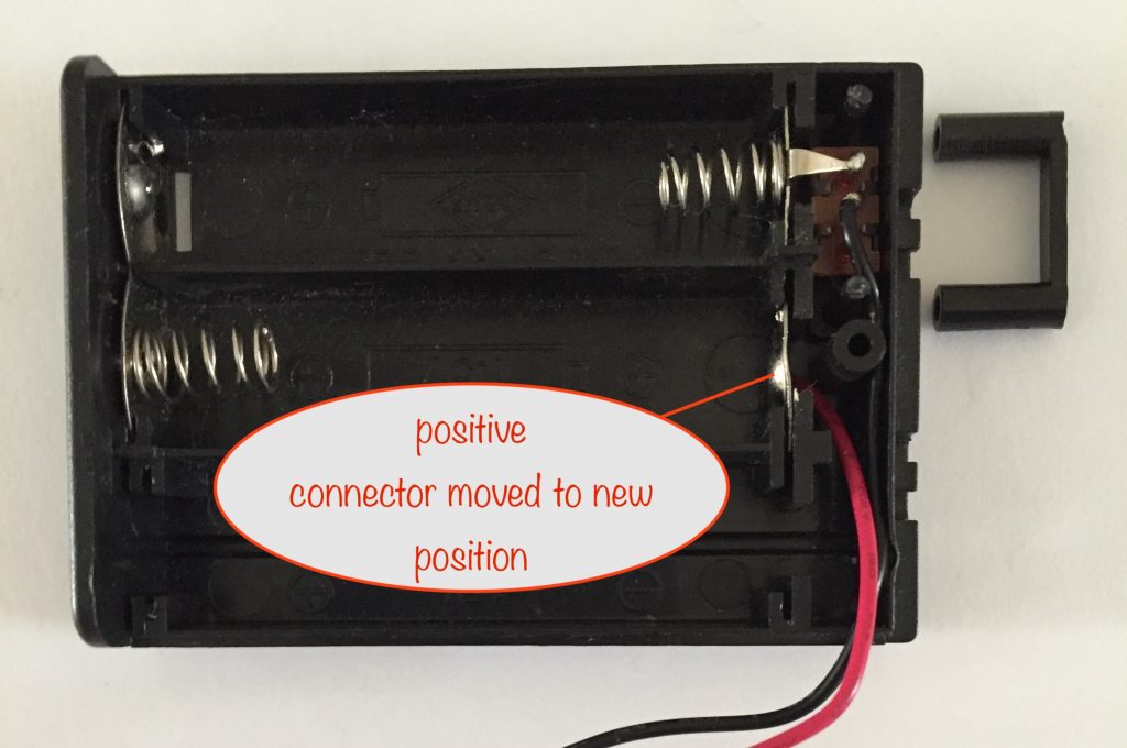
The goal here is to leave one battery slot empty for the stripboard holding the circuit and to shift the positive connector over one slot and place it at the other end.
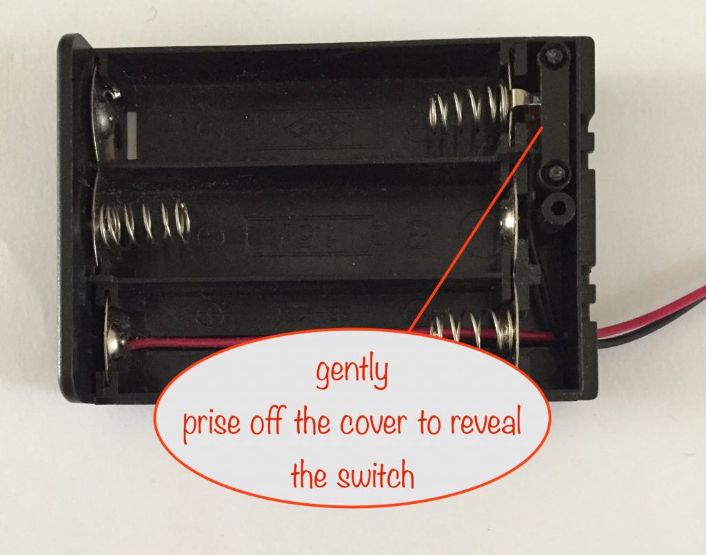
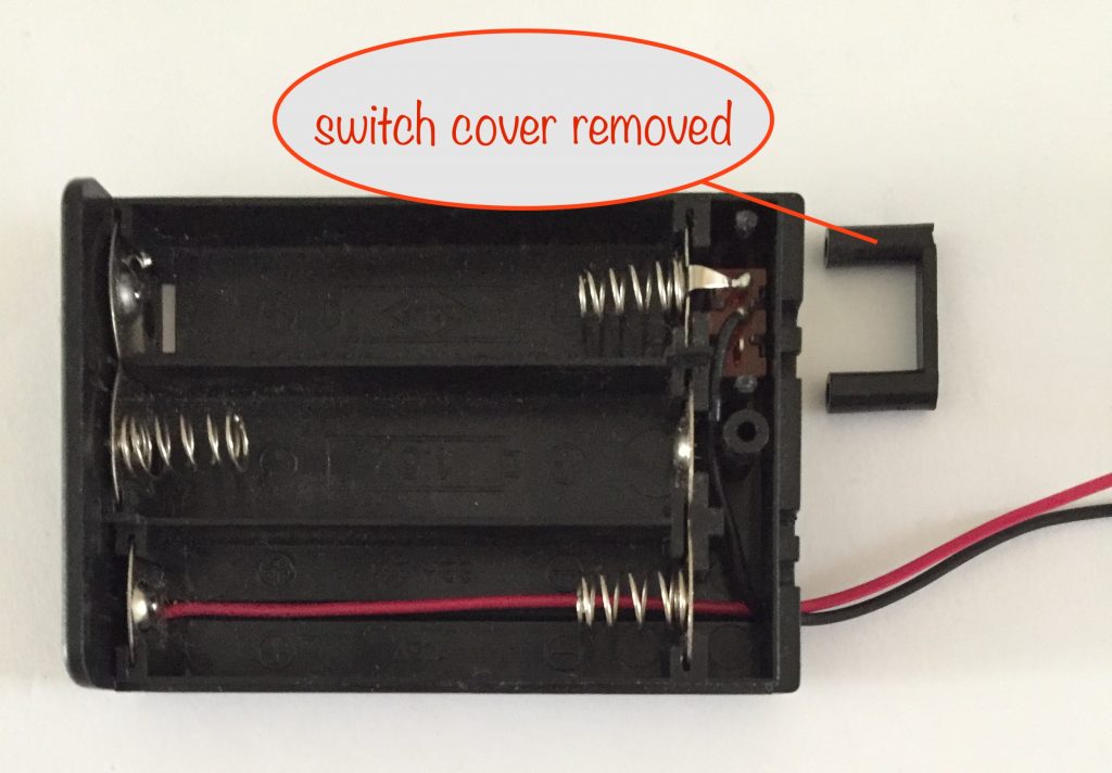
The first step is for you to carefully prise off the cover of the switch compartment. If it’s stubborn, you may have to use a small screwdriver to break where they’ve heat-sealed the tops of the plastic pillars to the cover.
Put the cover to one side as you’ll be puting it back later.
In the next step, you’ll remove the positive connector from its retaining slots and the two-in-one connector at the other end, ready to be move the positive connector to its new position.
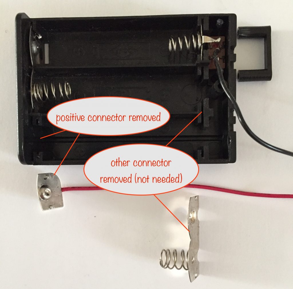
Don’t throw that two-in-one connector away – put it in your box of bits as it might come in handy for you to use for something else in the future.
You can now put the positive connector into its new position as shown below.
Preparing to solder the switch wires
First, you have to disconnect the existing negative terminal and the black wire from the switch:
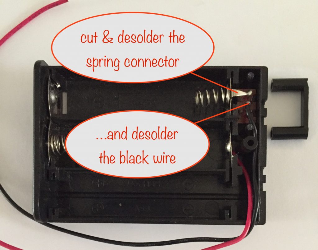
With them desoldered and disconnected you can now temporarily remove the switch and solder the yellow, purple and blue wires:
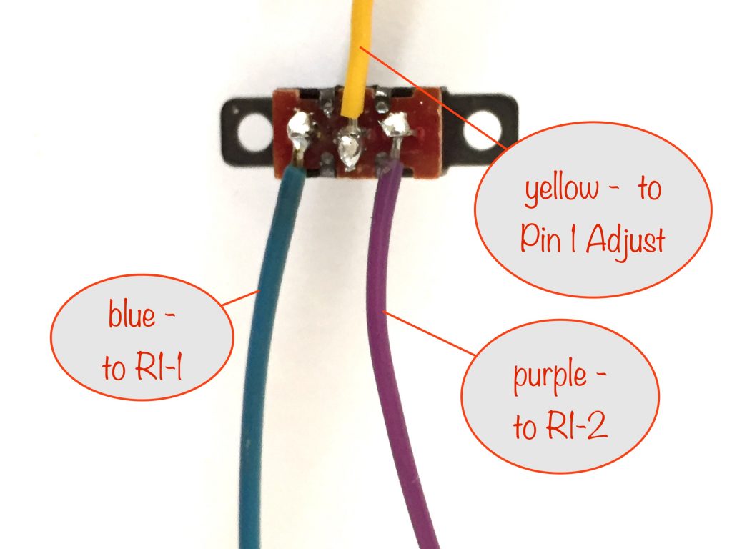
It makes sense to me to use the left switch position (the one marked ‘off’) for charging the lower capacity batteries and vice versa, so follow the colour coding of the wires to do the same.
Next, solder a black wire to the negative battery box spring connector. Make sure it doesn’t stand proud and get in the way of the switch terminals and switch cover when you come to replace it.
To allow for mistakes, make sure all the wires are a bit longer than needed. It’s easier to trim them down to size than to desolder and add new ones.
Stripboard layout
Here’s the stripboard layout of the circuit. Note that the LM317T back is showing with the front facing away, putting the Adjustment pin 1 on the right.
(click to see larger in new tab)
As a 25Ω resistor isn’t a commonly available value, R1-2 is actually two resistors in series – a 15Ω and a 10Ω (R1-2a and R1-2b).
Build the stripboard and solder the wires as shown:
(click for larger image in new tab / window)
Connecting the wires
Connect up the wires to the stripboard, cutting their lengths down to size, allowing for the twists and turns of routing them around the various obstacles. It’s better to err on the long-ish side:
- battery box negative (black)
- battery box positive (red)
- switch centre (yellow)
- C/10 charging resistor R1-1 (purple)
- C/10 charging resistor R1-2 (blue)
- twin leads for solar panel (red and black)
I’d recommend using a 2.1mm dc power connector socket on the solar panel wires so you can easily connect and disconnect the solar panel. Many of them come with a 2.1mm plug and if yours doesn’t, it’s easy enough to solder one on.
That should have finished the build, now on with testing.
Testing
Before final assembly, test that everything works ok:
- connect the solar panel
- flick the switch to the correct position for the battery capacity you’re charging
- put in 2 AA rechargable batteries with a capacity as per your choice of R1
- leave the solar panel where it gets full sunlight
The green LED should come on indicating that enough volts are present for charging the batteries. Now give it a few hours and, as long as the batteries weren’t really drained, the red LED should come on indicating that they’re fully charged.
If the batteries were really drained you’ll have to wait up to 10 hours (full sunlight) for them to reach full charge.
Note that, despite the correct calculation of the values for the voltage divider resistors, R3 and R4, the tolerances involved mean you might need to add another resistor.
- If the red LED never comes on, despite the batteries reaching the full charge voltage of 2.9 – 3V, you’ll need to add one between ground and R4.
- If the red LED comes on too soon, before the batteries reach full charge voltage, you’ll need to add one between R3 and TLV431 Ref .
The value of the additional resistor will likely be 50Ω or less. So lift the leg of the relevant resistor and try various values in series until you hit the sweet spot with the red LED coming on at around 2.9 to 3V.
When you’ve found the right value, tidy things up by soldering them together like I have with R1-2a and R1-2b.
Final assembly / finishing touches
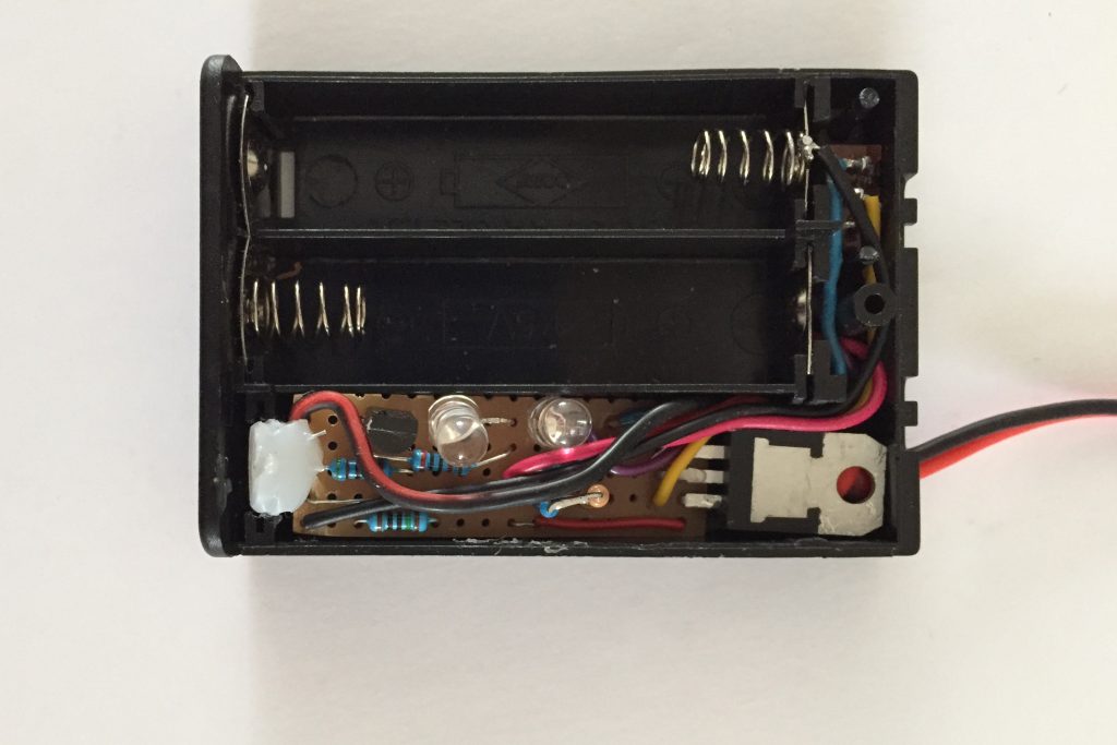
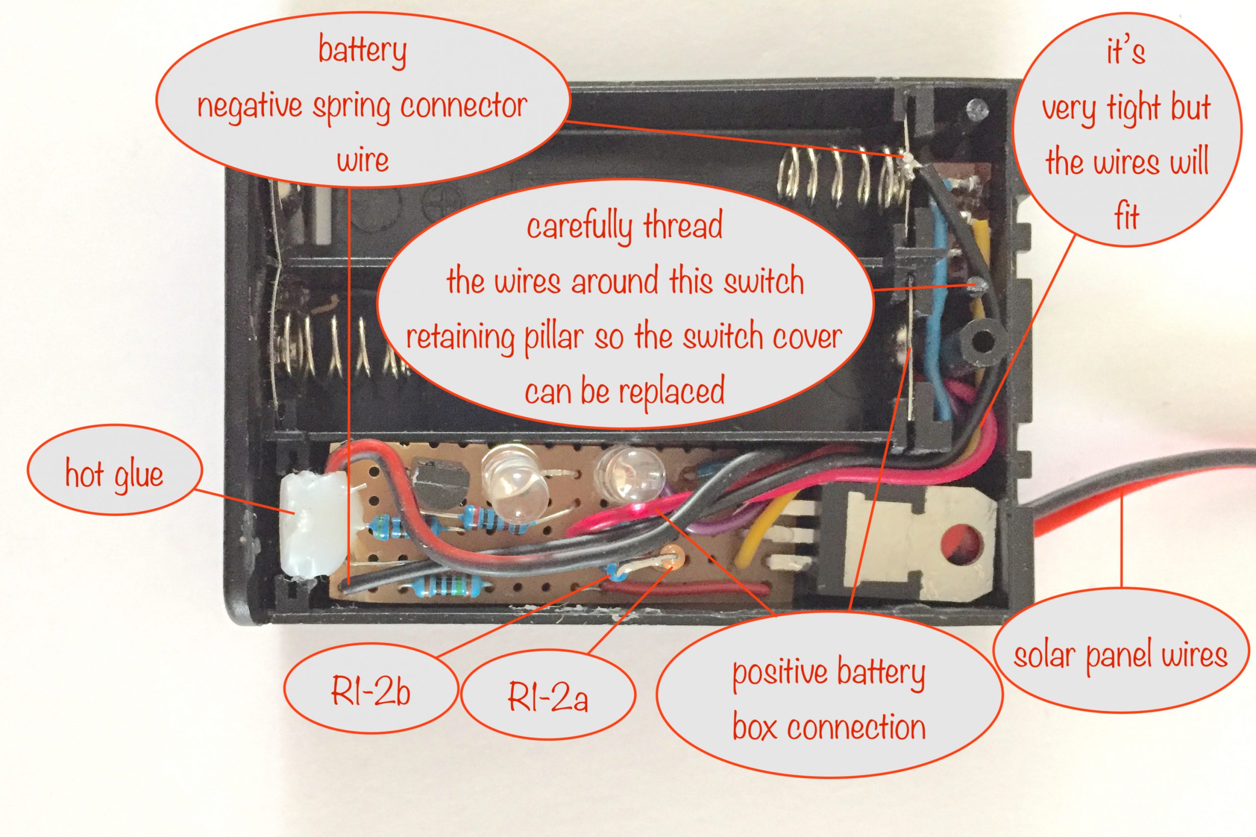
Once tested and you’re sure it’s working, you can now bunch all the wires from the stripboard together and fit them neatly under and beside the LM317T as shown in the photo above.
Replace the switch cover, using a small watchmaker screwdriver to tweak the position of the wires around the retaining pillar as you go. Make sure you don’t accidently damage the insulation!
As the last step for the circuit, you can apply some hot glue to hold the stripboard in place.
Making the LEDs visible
With the battery box cover in place, how do you see the LEDs? Simple, you drill a couple of 5mm holes in the case to line up with them.
When you’ve drilled them, put a piece of sticky tape on the inside to cover the holes. Then turn over the cover and put a few drops of UV glue into each hole (the sticky tape stops it running out).
You can now set the glue and remove the sticky tape leaving you with a great finished project.
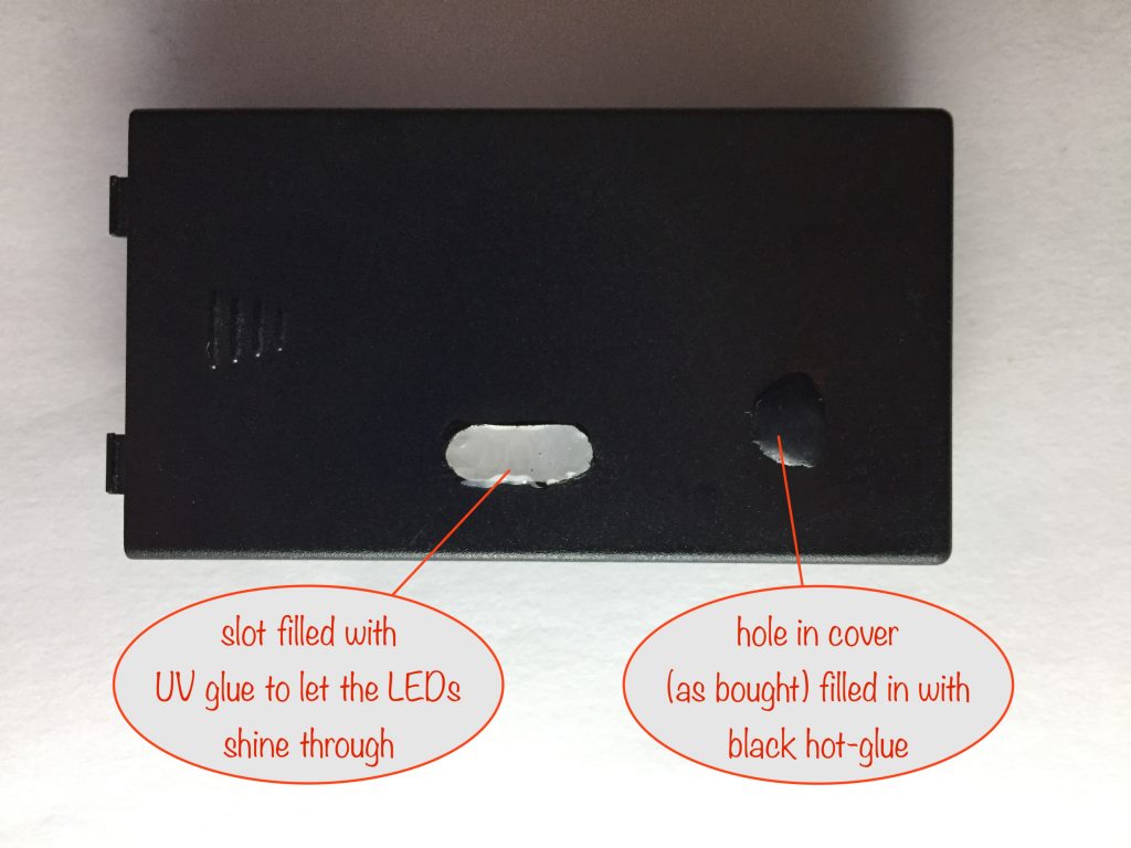
If you misplace the holes (like I did) turn them into a slot and fill that with UV glue instead. The slot takes a lot more glue, so don’t do as I did!
Remember the old adage, “measure twice, cut once“!
The last thing I did was to plug the hole in the cover (that’s how mine came) with some black hot-glue.
And in conclusion
Thanks for having followed along and, even if you haven’t built the project, I’m sure you’ve learned a few things on the way.
I’d love to hear what you think, so please drop off a comment. If you did build it, let us all know how it went.
Thanks!
Battery capacities, resistor value(s) and solar panel power for C/10 charging
Find the 2 battery capacities you’ll be charging in the table below to get the values for R1-1 and R1-2. Remember, once you’ve done that, you can still charge higher capacity batteries – they’ll just take longer.
The minimum wattage of the solar panel you’ll need depends on the charging current needed for the highest capacity of those batteries (plus a little extra for the green LED). But never mind that, just get a 6 Volt 2 Watt solar panel and it will cover everything here and give you some spare capacity for days when it’s not quite so sunny.
| Battery Capacity (mAh) | C/10 current (mA) | Nearest R1 value (Ω) | Charging current using R1 (mA) | 6V Solar Panel (Watts) |
| 500 | 50 | 27 | 46 | 0.5 |
| 550 | 55 | 24 | 52 | 0.5 |
| 650 | 65 | 20 | 63 | 0.5 |
| 700 | 70 | 18 | 69 | 0.5 |
| 750 | 75 | 18 | 69 | 0.5 |
| 800 | 80 | 16 | 78 | 0.6 |
| 900 | 90 | 15 | 83 | 0.6 |
| 930 | 93 | 15 | 83 | 0.6 |
| 950 | 95 | 15 | 83 | 0.6 |
| 1000 | 100 | 13 | 96 | 0.7 |
| 1100 | 110 | 12 | 104 | 0.7 |
Resistor calculation
If you need to, you can calculate the value of R1 yourself using the formula:
R1(Ω) = 12500 / battery capacity (mAh)
Solar Panel power calculation
I wouldn’t bother with this. As mentioned above, I’d just get a 6 Volt 2 Watt solar panel that will cover everything here and give some spare capacity so that it still charges on not-so-sunny days.
But if you want to calculate the solar panel power yourself, it’s given by:
Solar Panel Watts = Solar Panel Volts x (actual charging current for highest capacity battery as given by R1 + green LED current)
For 2 batteries and a 1300mAh battery (actual R1 charging current is 125mA), it’s:
Watts = 6V x (125mA + 10mA) = 0.81W
The next highest commonly-ish available Solar Panel is 0.7W
Other projects in the Nifty Hobby Projects for LEDs and Solar series (so far, more to come very soon):
- Flasher Memory Aid
- Dark-activated Switch
- 5 LED String
- Fibre Optic Display
- Mini Sparkles Colour-changing LED Fibre Optic String
- Solar Lithium Ion Battery Charger
- Solar NiMH Battery Charger for 6 AA batteries
- Solar NiMH Battery Charger for 2 AAA batteries
- Timer-delay Off Switch
- 4-LED Porch Light
- 10-LED Bedside lamp
- Mini Camping / Bedtime Reading Lamp
- Main page with links to where to buy stuff
Read all about NiMH rechargeable batteries on the Wikipedia Nickel-metal hydride battery page (opens in new tab / window)