this bedside lamp is another module in the Nifty Hobby Projects for LEDs and Solar series written by team-member Mark Ridley
This tutorial shows you how to make a bedside lamp that’s powered by 3 rechargeable AA or AAA NiMH batteries. It’s really easy to make, too!
As it’s portable it also makes a great hurricane lamp or emergency lighting if you have a power cut.
Description
If you use the recommended 2000mAh batteries, you’ll get around 10 hours of use before you need to recharge the batteries. At 15 minutes per day, that’s an amazing 40 days!
Using renewable energy is really important as we try and counter the effects of global warming and this is a great use for the batteries you’ve charged with the NIMH solar charger you built earlier.
And it also reuses a milk container that you would otherwise have recycled. Excellent!
Circuit Diagram
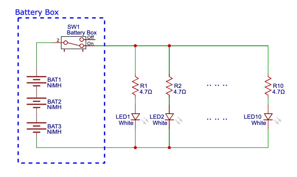
Circuit notes
The 3 batteries in series gives 3 x 1.5V = 4.5V (when no current is being drawn). The ultra bright LEDs have a forward voltage of 3.3V and a maximum current rating of 25mA.
The voltage that needs to be dropped across the current limiting resistor is:
4.5V – 3.3V = 1.2V.
Using Ohms Law will give us the resistor’s value:
1.2V / 0.025A = 48Ω
Note that the voltage of the batteries will drop a little once current is being drawn so it’s safe to use 47Ω, the nearest value to 48Ω.
Components list
The resistors are ¼Watt. 1%, 5% or 10% tolerance are all good.
- 10 x 47Ω resisistors
- 10 x LEDs – 5mm ultra bright diffused with 3.3V forward voltage and 25mA maximum current
- AA battery box with switch and 3 battery slots
- 3 x rechargeable AA batteries, recommended 2000mAh capacity
- 1 length of twin wire approx 30cm (10 inches) long to connect the stripboard to the battery box wires
- 1 length of stripboard, 33 columns by 3 or 4 rows
- 2 short lengths of 2.4mm diameter heatshrink tubing
- 1 length of wood batten / plywood around 12cm (5 inches) long
Tools etc. you’ll need:
- 18 Watt soldering iron, 25 Watts at a push
- “Helping Hand”
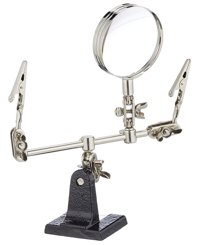 – invaluable aid while soldering or gluing
 - Wire strippers covering 26 to 16 AWG
- Side cutters
- Snipe-nosed pliers or 3 or 4mm drill bit
- Glue gun for fixing everything in place
Stripboard layout
Here’s the stripboard layout of the circuit.
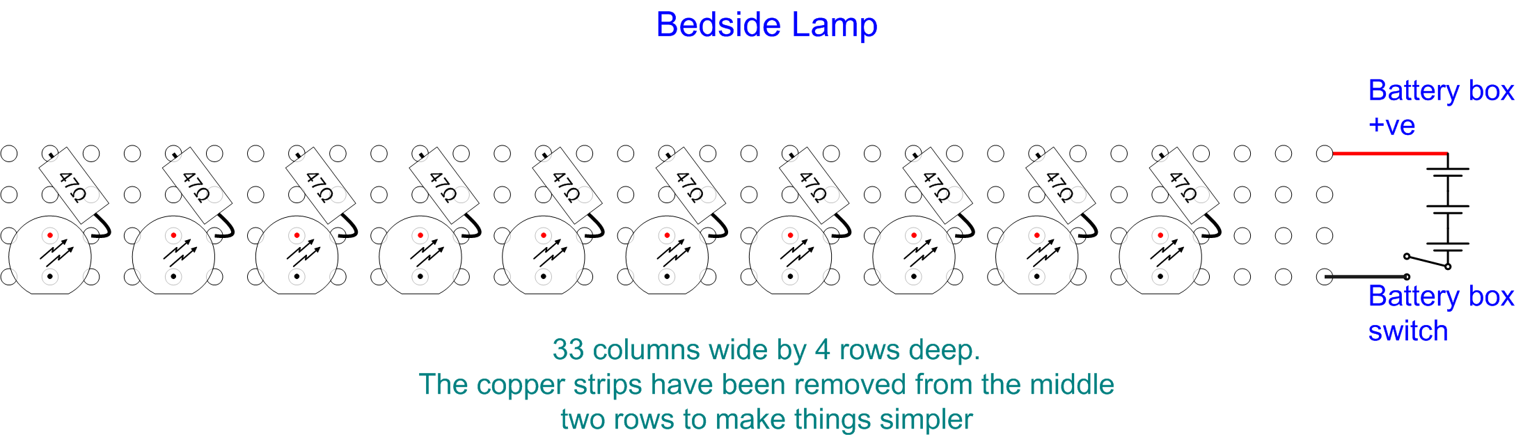
(click to see larger in a new tab)
As you can see, it’s really straighforward and easy to do.
Preparing the stripboard
You can either use a stripboard cutter (a 3 or 4 mm drill bit will do the job) to cut the track between each LED’s positive leg and the next or you can just remove the strip of copper from the row where they go.
I got carried away and removed the copper strips from both of the middle rows. To remove it / them, heat up the edge of a strip (to soften the glue that holds the copper to the stripboard) and persuade the copper to lift (I used a small watchmaker’s screwdriver to lift it initially).
Once the edge has lifted, grasp it with your snipe-nosed pliers and, while still heating the strip with your soldering iron, lift the copper strip away, moving the soldering iron along the strip as you go.
Placing and soldering the components
When you’ve done that, you’re ready to place the resistors and LEDs. Look at the following photo of the completed stripboard so you can follow along with the instructions below.
I did them one pair at a time. I soldered the negative (short) leg of the LED to the bottom row first and then heated up the solder while pressing the LED so it was flat against the stripboard.
If you like, you can get creative and and alternate each LED so they point a little up and a little down. Doing that will spread the light better.
Next I placed the resistor at an angle on the top row, so the body of the resistor sat just off the stripboard and was bent over at 45 degrees. I then threaded the other leg of the resistor through the hole in the second row from the bottom, beside that first LED and then soldered that leg to the positive leg of the LED.
It’s easier to do than to describe, so have a look at the underside of the stripboard as well to see what I mean:
(click for larger image in a new tab)
With that done I then made sure the resistor was at 45 degrees to minimise them getting in the way of the light before soldering the other leg to the top row.
So do that for all 10 pairs of resistors / LEDs and then solder the twin wires to the stripboard ready for connecting up to the battery box wires via the wooden support batten and milk container lid.
Fixing the wooden batten
The purpose of the batten is to hold the stripboard in place in roughly the centre of the milk container so that you get an even, diffuse glow.
When you’ve done that, butt the length of wooden batten up against the end of the stripboard and hot-glue it in place. You can then hot glue the twin wire to the batten.
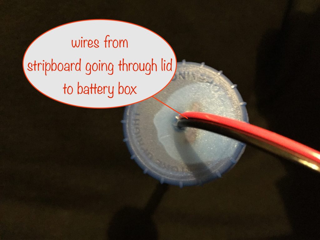
Make a small hole for the twin wire in the lid of the milk container and thread the twin wire through.
When you’ve done that, you can hot-glue the wooden batten to the lid. Take care that you orient it so that the LEDs point in the right direction when the lid is tightened.
I prefer them to point directly away from the milk container’s handle so that when it’s on its stand (the stand is the battery box – see photos later on) they point upwards.
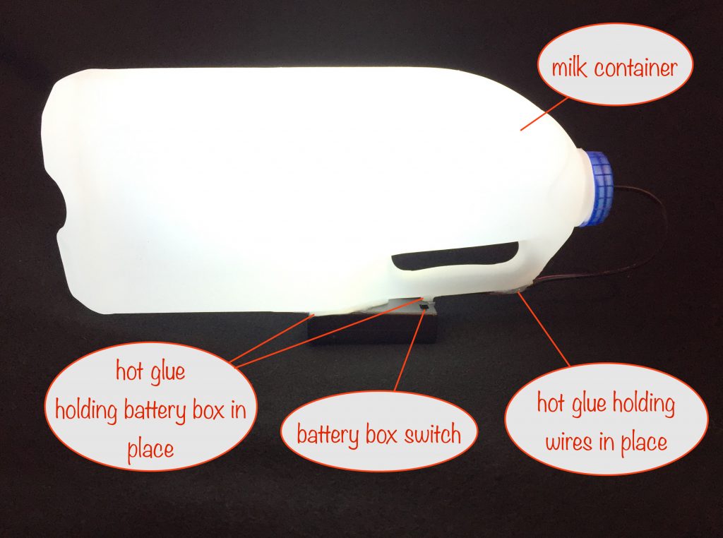
This is what the top of the lid now looks like:
Mounting the battery box
Before doing the following, check that your circuit works as it’s much easier to correct any faults now than after you’ve mounted everything!
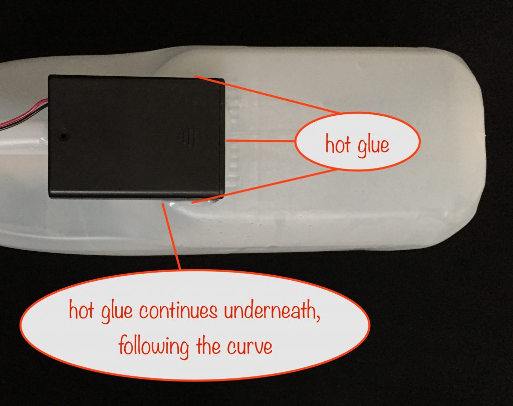
The battery box is hot-glued to the milk container as shown. It’s weight and position makes it an ideal stand for the bedside lamp. Make sure you hot-glue it as shown with its lid facing outwards so that you’ve got easy access to the batteries.
Mounted like that it places the switch on the other side so it’s easy to get at.
The last thing for you to to do is to connect up the twin wires from the circuit to the battery box wires. You’ll need to use heatshrink tubing (or electrical insulation tape) to cover the joints.
Once you’ve done that, you can then hot-glue the wires to the handle of the milk container:
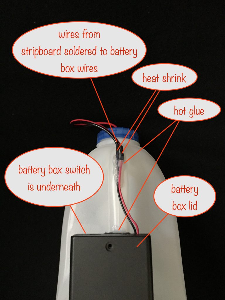
Note that the handle is the only place for the battery box that makes logical sense. With it placed there, it conveniently makes a base for the bedside lamp as its weight makes it the natural balance point.
You can also carry it around by the handle like a hurricane lamp and, with the wiring hot-glued as shown, you can loop the twin wire over a nail / hook as an alternative to standing it on the base.
Mods you can make
Use fewer LEDs to make a nightlight in a smaller milk container. With 2 LEDs and using 2000mAh batteries, your nightlight will last around 5 nights at 8 hours per night. That gives you plenty of time to charge up replacements with your solar charger!
Other projects in the Nifty Hobby Projects for LEDs and Solar series (so far, more to come very soon):
- Dark-activated Switch
- 5 LED String
- Fibre Optic Display
- Mini Sparkles Colour-changing LED Fibre Optic String
- Solar Lithium Ion Battery Charger
- Solar NiMH Battery Charger for 2 AAA batteries
- Solar NiMH Battery Charger for 2 AA batteries
- Solar NiMH Battery Charger for 6 AA batteries
- Timer-delay Off Switch
- 4-LED Porch Light
- Mini Camping / Bedtime Reading Lamp
- Main page with links to where to buy stuff