the dark-activated switch is another mix ‘n match module in the Nifty Hobby Projects for LEDs series (tbc)
This module supplies power to the various indoor LED display modules that are covered elsewhere in this series (tbc).
It senses when it’s dark and switches on power so they light up. The level of darkness that triggers the switch-on is adjustable and there’s an over-ride switch so you can have them stay on all the time.
Battery box slide switch
The slide switch has two positions, marked “On” and “Off”:
- On = power permanently delivered to the load
- Off = power to the load is off until darkness sets in
About powering the module and the power it can deliver
To keep the design simple, the dark-activated switch doesn’t have a built-in voltage regulator. This means you need to supply it with the right voltage. Anywhere between 3.6 and 4V is fine. Just be aware that as the voltage you supply climbs above 4V, so the lifetime of the LEDs in your displays will be shortened.
Possibilites for powering the dark-activated switch
- 5V DC from a mains adapter (wall wart to those in the USA) – with a 1N4001/2/3/4 diode in the positive line. The diode will drop around 0.85V (under loads used in these projects) and bring the voltage down to the approx 4V. This is what I do.
If you can only get a 6V DC mains adaptor, use two 1N5819+ Schottky diodes in series (for a voltage drop of 2 x 0.9V = 1.8V, leaving 4.2V) - 4.5V from 3 fully charged NiMH batteries in series – this will drop quickly under load and so is ok
- 4.2V from a fully-charged Lithium Ion battery. Again, this will drop quite quickly and so is ok.
Power that the dark-activated switch can deliver
With the MOSFET used, the module can safely deliver more than the limit imposed by the 1N4001/1N5819+ (1 amp) up to around 2 or 3 amps.
If you’re using a power source without a series diode(s), note that the power that can be delivered is limited by the ability of the MOSFET to dissipate heat within the confines of the battery box used, so treat that as a maximum.
Of course, your power source must be able to safely deliver the current your load wants to draw.
Examples using display modules
The LED display modules here all use colour-changing LEDs that don’t need current limiting resistors. The reason is that they incorporate a tiny microcontroller that does the current limiting.
If you want to use other types of LEDs in your displays you’ll need to include a resistor in series with each LED whose value depends on the voltage output by the dark-activated switch and the current capacity of the LEDs you’re using.
The amount of current a single colour-changing LED will draw, at the voltages given above, averages out between 20mA and 35mA. The upper end might seem rather high but it’s nothing to worry about as that’s when the microcontroller inside the LED has switched on the R,G and B to make white.
I’ve tested this over a range of voltages (highest was 4.5V) and different numbers of colour-changing LEDs, up to 33. The peak current measured was 866mA (when all 33 were white) and that’s well within the safe limits of the MOSFET and below the 1A limit imposed by the diode(s) in the power-in line of the mains adapter.
Circuit Diagram for dark-activated switch
You get a better range for setting the dark-on point if you use a 10kΩ resistor for R1 instead of the 1MΩ shown in the diagram (and photos).
I’ve actually started using the 10kΩ for all dark-activated switches I’ve built since writing this tutorial.
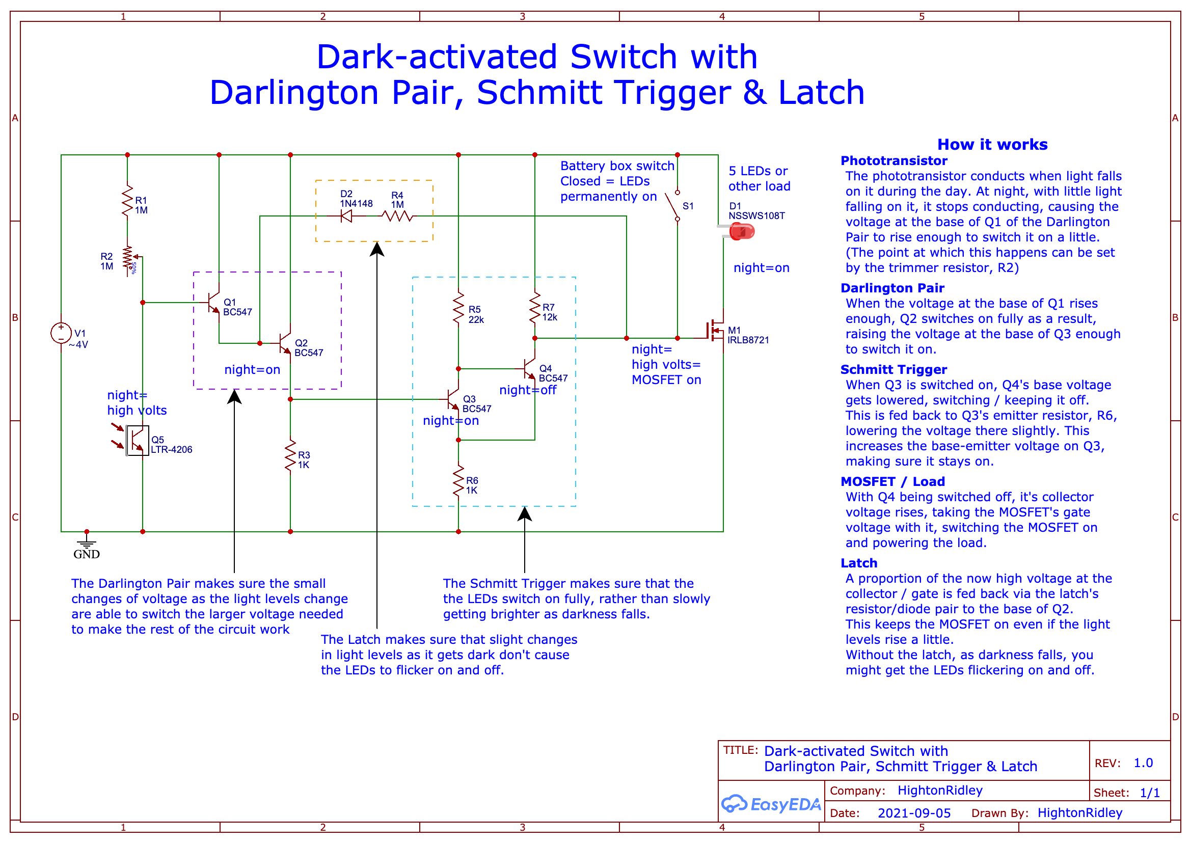
Edit: R1 is now 10kΩ
How the dark-activated switch works
This section describes the various parts of the circuit and the operation of each. Skip down to the build section if you just want to get on making it 🙂
Phototransistor
The phototransistor conducts when light falls on it during the day. At night, with little light falling on it, it stops conducting, causing the voltage at the base of Q1 of the Darlington Pair to rise enough to switch it on a little. (The point at which this happens can be set by the trimmer resistor, R2)
Darlington Pair
When the voltage at the base of Q1 rises enough, Q2 switches on fully as a result, raising the voltage at the base of Q3 enough to switch it on.
Schmitt Trigger
When Q3 is switched on, Q4’s base voltage gets lowered, switching / keeping it off. This is fed back to Q3’s emitter resistor, R6, lowering the voltage there slightly.
This increases the base-emitter voltage on Q3, making sure it stays on.
MOSFET / Load
With Q4 being switched off, it’s collector voltage rises, taking the MOSFET’s gate voltage with it, switching the MOSFET on and powering the load.
Latch
A proportion of the now high voltage at the collector / gate is fed back via the latch’s resistor/diode pair to the base of Q2. This keeps the MOSFET on even if the light levels rise a little.
Without the latch, as darkness falls, you might get the LEDs switching on and off over a period if the light levels change (you might still get a little flickering for a few seconds but the effect is minimal).
Building your dark-activated switch
Don’t be put off by what follows – it might look complicated with lots to do but it isn’t. It just looks that way because every step of the way is explained with pictures so that complete novices are helped as much as possible.
First off, here’s a list of components and tools you’ll need for the project.
Components list
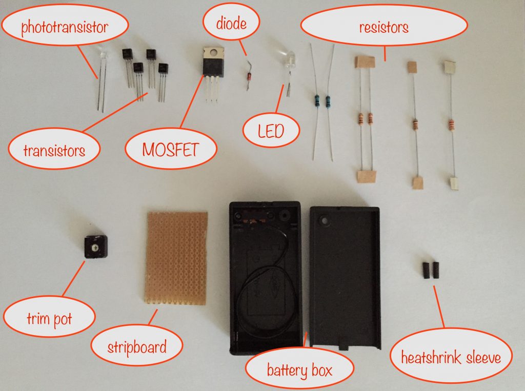
NB All resistors are ¼Watt. 1%, 5% or 10% tolerance are all good. It so happens that I had the two 1MΩ resistors at 1% tolerance and the rest at 5% tolerance.
Also, you’ll see I’ve got a pre-used 1N4148 diode. (I ‘harvested’ it from a circuit board from an old broken landline phone I had in my box of bits.)
- 1 x LTR-4206 phototransistor
- 4 x BC547 NPN general purpose transistors
- 1x IRLB8721 N-channel MOSFET (TO-220 package)
- 1 x 1N4148 diode
- for testing the output, a LED with a 220Ω (or thereabouts) current-limiting resistor soldered to one of the legs
- 2 x 1kΩ resistor
- 1 x 12kΩ resistor
- 1 x 22kΩ resistor
- 2 x 1MΩ resistor Edit: one of these is now a 10kΩ resistor as per the notes above the circuit diagram
- 1 x 1MΩ variable resistor (aka trim pot)
- 1 x Stripboard, 17 columns by 11 rows (fits neatly in the battery box)
- 1 x Battery box with switch
- 1 x Power input lead – twin flexible, multi-strand 20 swg is good
- 1 x Power output lead – twin flexible, multi-strand 20 swg is good
- Various short lengths of wire for making stripboard connections
- Heat shrink sleeve – a couple of short lengths of 1.6mm diameter sleeve for the legs of the phototransistor.
Tools etc. you’ll need:
- 18 Watt soldering iron, 25 Watts at a push
- Desoldering pump / solder wick – in case of mistakes!
- “Helping Hand”
 – invaluable aid while soldering or gluing
 - Wire strippers covering 26 to 16 AWG
- Side cutters
- Small snipe-nose / needle-nose pliers
- Set of watchmaker-style screwdrivers for adjusting the trim pot – also for general poking, prodding and levering
- Glue gun for fixing the phototransistor and power-in and -out leads in place
- Small hobbyist drill with a 2mm, 3mm, 4mm and 5mm drill bit
Preparing the battery box for your dark-activated switch
Stripping it down
There are two types of PP3 battery boxes commonly available that are ideal for this project:
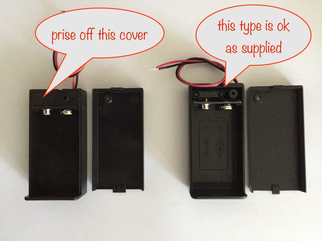
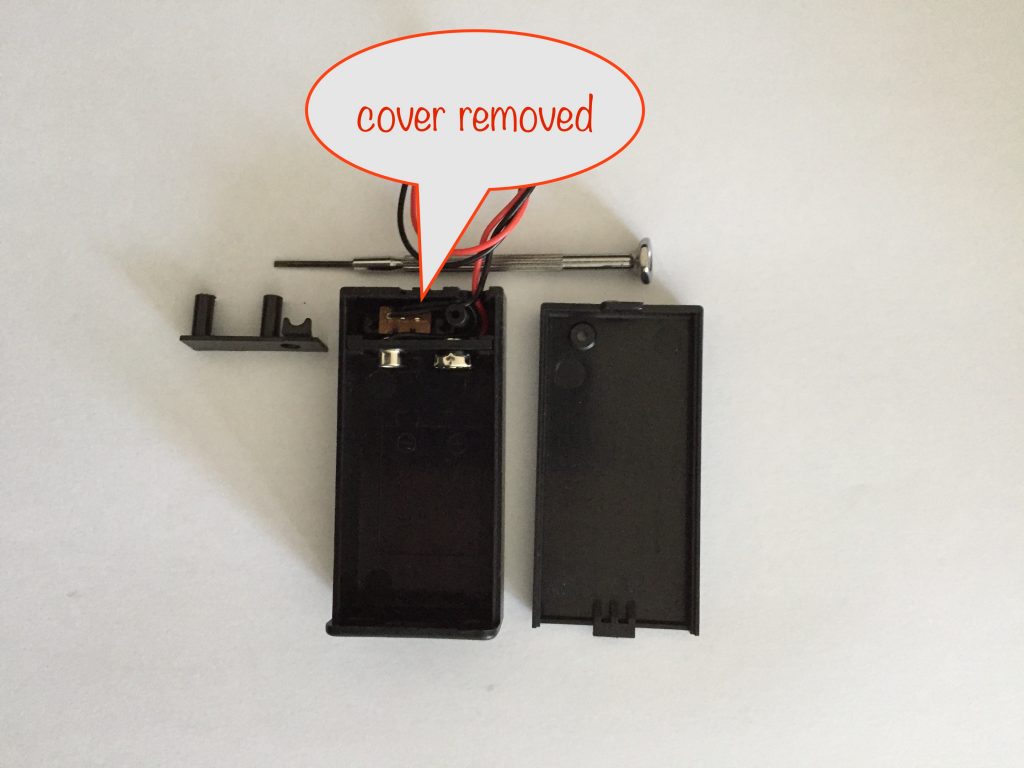
If you have the type on the left, carefully prise off the cover with a small watchmaker-style flat-bladed screwdriver to reveal the switch and wires. You can then put the cover into your recycling bin as it’s of no further use.
Whichever type you have, you now have to pull the wires out of the hole and back into the box. Push them through the hole until you can grab them and pull the rest of the way.
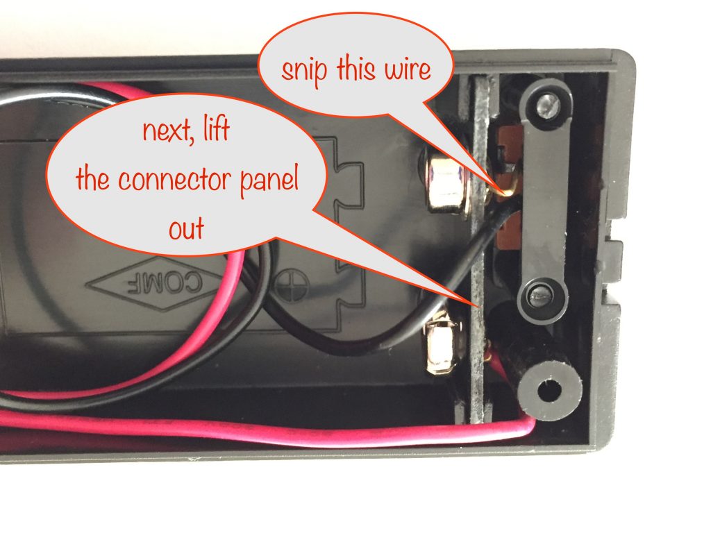
Use your side-cutters to snip the exposed wire connecting the switch to the negative battery terminal. This means the switch won’t be held firmly in place – see below for how to fix that.
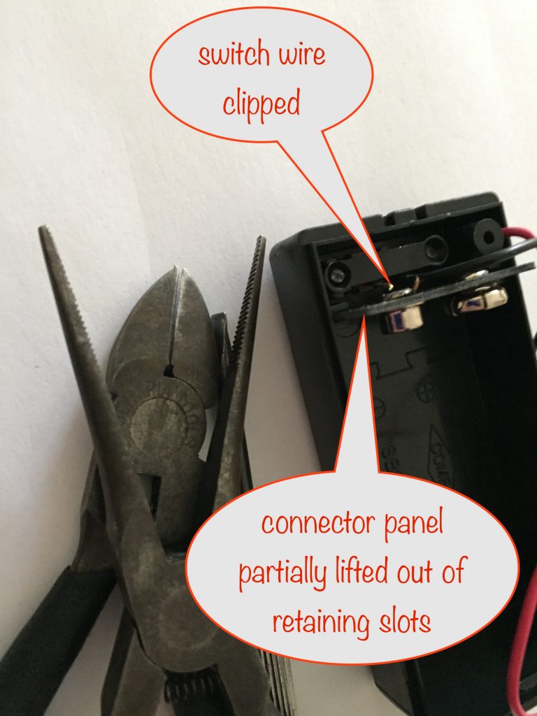
Now use your snipe-nose pliers and a larger watchmaker’s screwdriver to pull and lever the plastic panel holding the battery connections out from its retaining slots. You don’t need it anymore so put it into your box of bits for a future project.
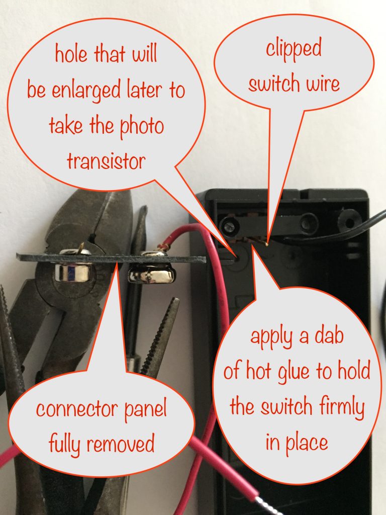
When you’ve done that, you’ll need to secure the switch in place with a dab of hot glue. Make sure you don’t use too much in case you cover up the small hole next to it – you’ll be enlarging it with a drill later on to accept the phototransistor.
Leave the black wire that’s connected to the switch – you’ll be using it later.
Drilling the holes in the battery box
You need a total of three holes – two of which already exist:
- one for the phototransistor – already exists but needs enlarging. You can do that now.
- one for the power in leads – already exists, may need enlarging.
- one for the power out leads – brand new. Leave for later, once you’ve got the components soldered onto the stripboard. That way you can make sure the hole is clear of all the components.
Tip: It’s always a good idea to drill a hole in stages.
Say you need a 5mm hole. Don’t set to with a 5mm drill bit right away, instead drill a ‘pilot’ hole first with, say, a 2mm bit. Next, enlarge it with a 3mm bit before moving on to a 4mm bit. Only then would you finish off the hole with the 5mm drill bit.
Also, when drilling plastic, make sure you stick to a slowish drill speed or you might melt it!
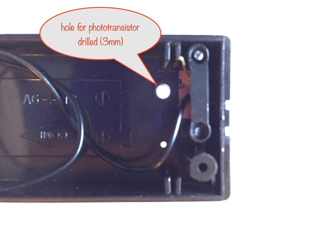
The phototransistor is to be placed (later) where the tiny hole is, next to the switch. Drill that tiny hole to enlarge it to 3mm and check that the photransistor almost fits. If it doesn’t go all the way through – that’s fine, we don’t really want it to. Instead we want it to be almost but not quite flush with the surface.
The existing hole you pushed the battery leads through is for the power-in leads. You might need to enlarge it to accept yours. Check for size and drill to what you need.
The power-out leads leave the battery box at the other end. If you want to have the hole close-ish to the center, make sure you leave enough distance so the leads don’t come into contact with the metal of the MOSFET, which may get quite hot.
Stripboard layout for dark-activated switch
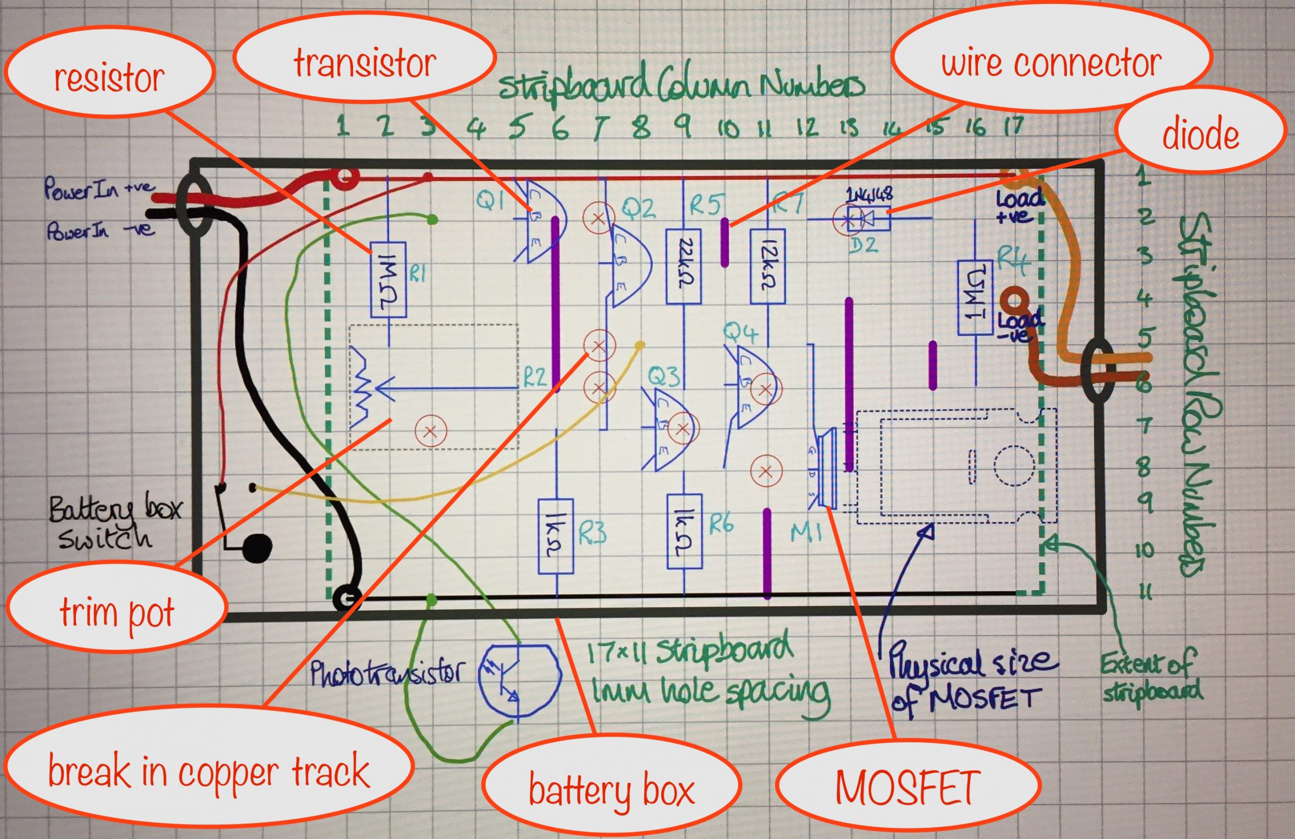
(copper tracks on other side)
Edit: R1 is now 10kΩ
Preparing the stripboard
Cut to size
You need to cut your stripboard to 17 columns by 11 rows. Cut down the 18th column of holes and along the 12th row of holes, leaving 17 complete columns of holes and 11 complete strips of copper.
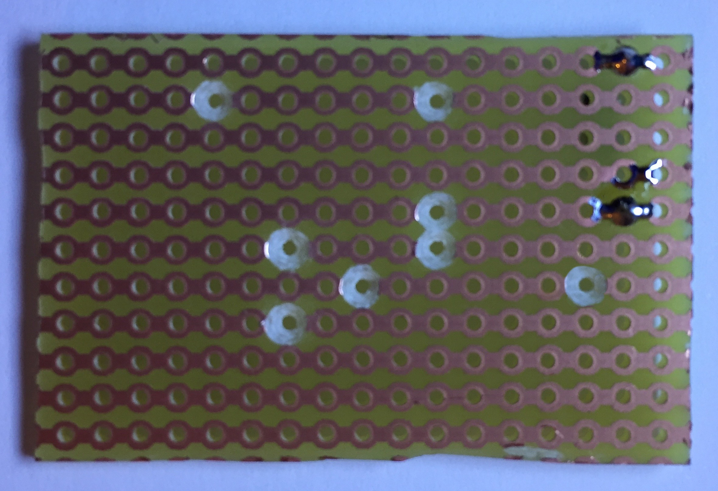
Cut the tracks where indicated
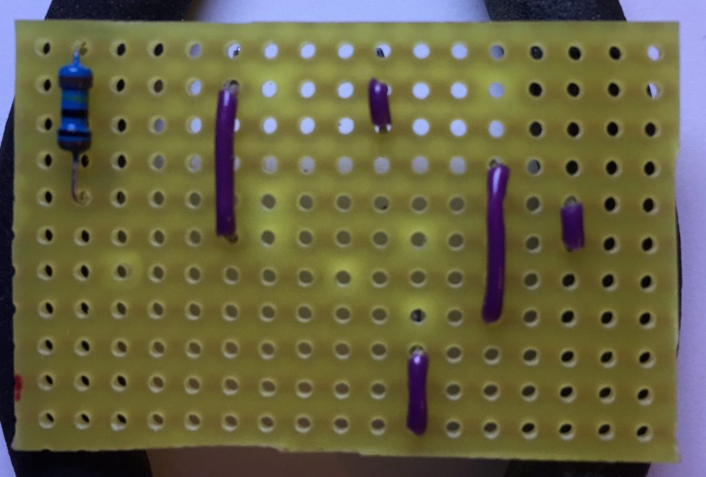
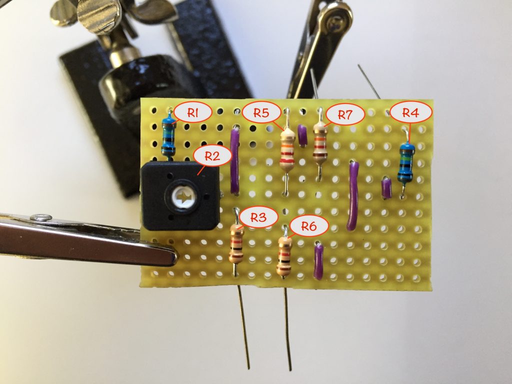
First, place and solder resistor R1 (1MΩ). That way, you’ve got a reference point for the top left of the component side and it’ll help stop you getting mixed up as you turn the board over ready for breaking the tracks.
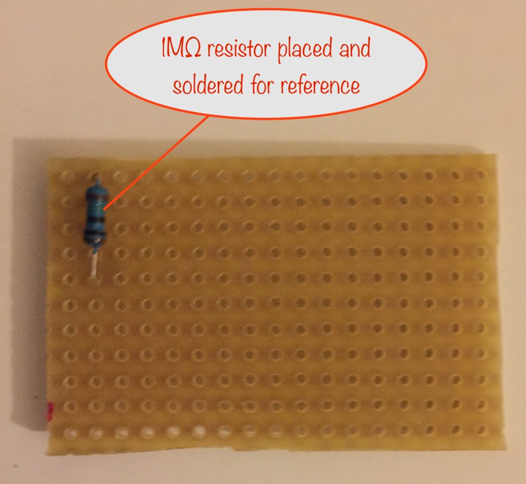
Edit: R1 is now 10kΩ
Make sure the resistor sits snugly against the board, with its body closer to the top. This is because the trim pot body overlaps the bottom leg slightly.
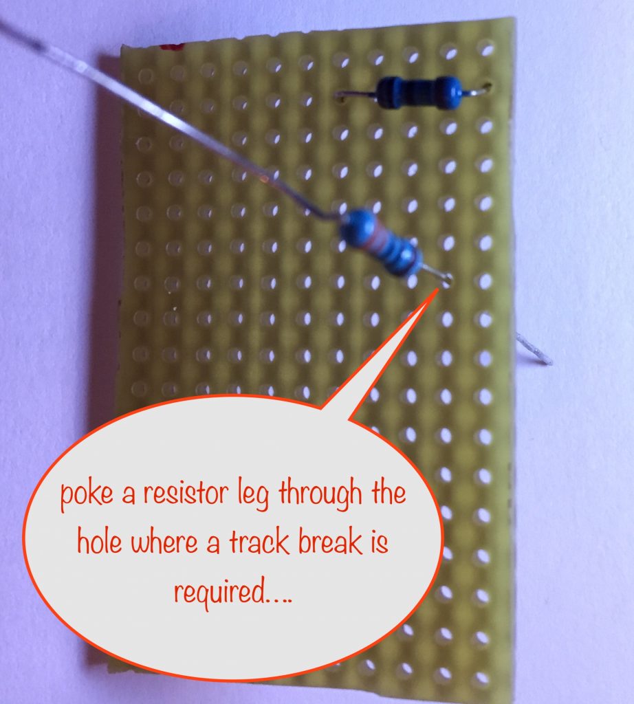
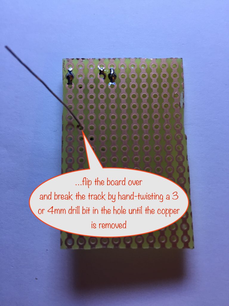
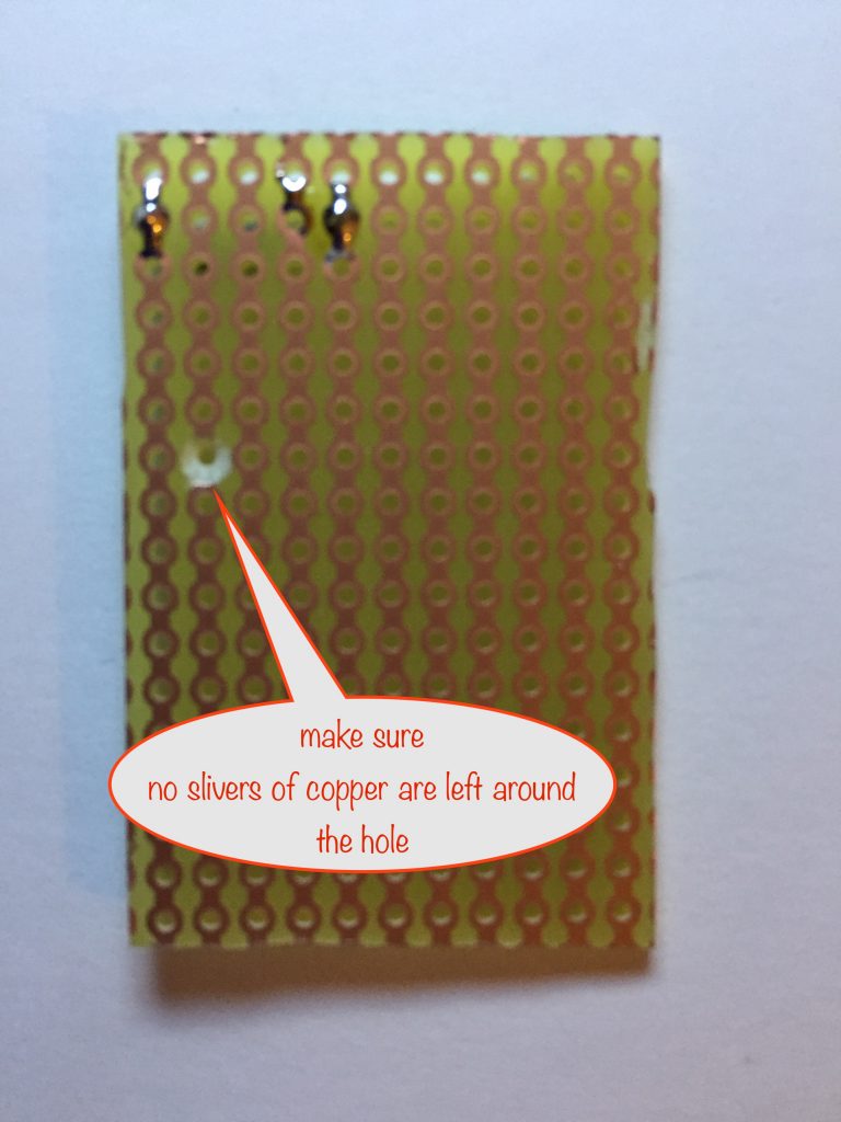
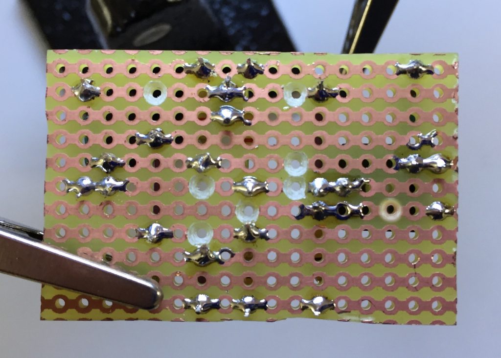
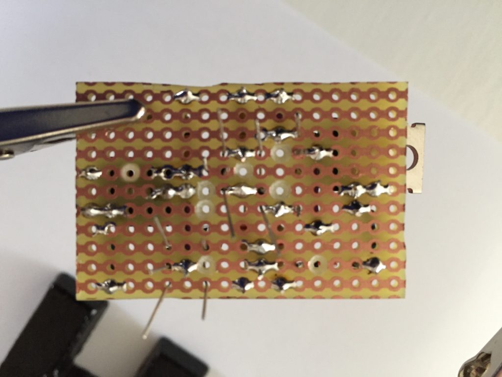
To make the breaks in the copper tracks place a 4, 5 or 6mm drill bit in the indicated hole and manually spin it. This will remove the coppper around the hole – but do check to make sure that there’s no slivers of copper left around the hole!
Now make the rest of the breaks – double checking each one before cutting the track. I’ve heard there’s a saying in the building trade – measure twice, cut once! Same applies here 😎
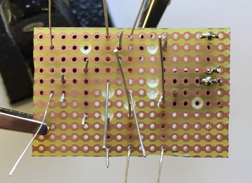
Place the wires that connect the tracks
Cut the 5 wires to length, strip and tin the ends and bend them over at 90° with your snipe-nosed pliers.
Place them one at a time, turning over the board to the copper side and ‘lock’ them in place by bending the tinned ends over at 45°.
Edit: R1 is now 10kΩ
Double check you’ve located them correctly before moving on to placing the first of the components, below. The reason for waiting is that when you start placing the rest of the components, it’ll give you a chance to correct any that are misplaced that you might have missed!
Place and solder the components
Soldering Tip 1: Don’t move a joint while the solder is still molten. Doing so can lead to a ‘dry joint’, which gives a poor / unreliable connection. Same goes for blowing on it – so don’t!
Use your snipe-nose pliers to bend the lead / legs of the components so that they reach the holes they’re meant for.
Make sure you place the 1MΩ resistor (R1, see above) before soldering the trim pot in place as the lower leg needs to go under it.
Place the rest of the resistors, locking each in place by bending their leads at 45°. Double-check their placement before soldering them and trimming their legs. This will keep things tidy.
Edit: R1 is now 10kΩ
Now the resistors have been placed, it’s time to solder them and the connecting wires.
Next, prepare the transistors and the MOSFET leg bends using your snipe-nosed pliers.
Note especially the placement of the bends on the MOSFET. Remember that it has to overhang the stripboard some to allow air circulation around the metal heatsink.
We’ll also place the 1N4148 diode now as well. Note that the black band of the diode is on the left.
As you place each component, turn over to the copper side of the board and bend its legs at 45° so it doesn’t fall out while you’re placing the rest.
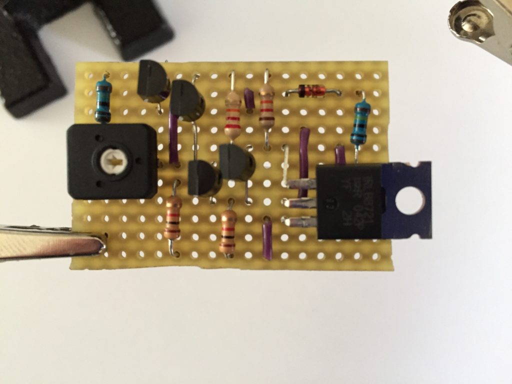
Take care with the MOSFET as it has to be bent over parallel to the stripboard. Make sure that when it is, the stripboard still fits comfortably inside the battery box, allowing room for placing the phototransistor. When checking, give it room so it doesn’t touch the plastic of the box. This is to allow air to circulate around the metal heatsink of the MOSFET to help keep it cool under load.
Before soldering, once again double-check your components are all in the right place.
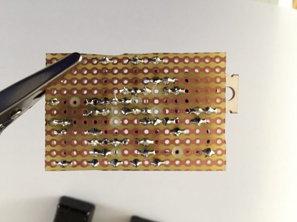
Check your soldering
Look over your soldering, making sure you haven’t accidently bridged over any of the tracks.
When you’re sure it all looks good, you’re ready complete the build.
Completing the build of your dark-activated switch
Almost there! Let’s just check the clearances and where the hole for the leads for powering the load can go. Slip the circuit into the battery box like this:
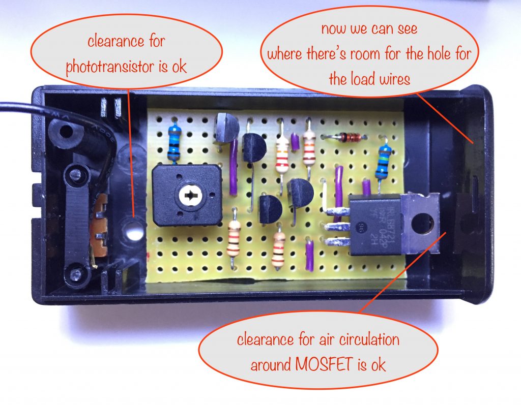
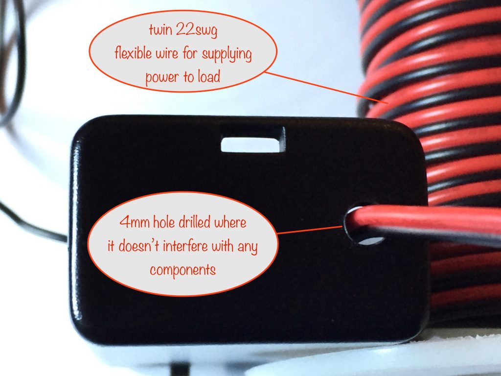
Drilling the hole for the load leads
The wire I’m using is twin 22 gauge and it fits just fine in the existing hole where the battery box leads went. So the hole I need to drill for the load leads can be the same size – 4mm
Preparing and soldering the power-in and power-out leads
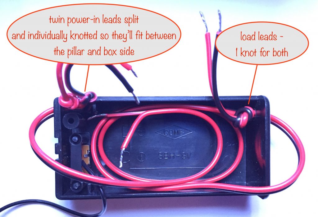
It’s always a good idea to make sure that when leads get pulled / jerked (which they will sometimes in normal use) the strain doesn’t get through to the connections on the stripboard. Knotting the leads on the inside of holes is a normal way of going about it.
First, cut off a couple of lengths of your twin leads (if that’s what you’re using), one for power in and one for power out. Split, strip and tin the ends of the wires to keep things tidy while you work. Then do the knotting like in the photo, leaving just enough wire to connect to the stripboard.
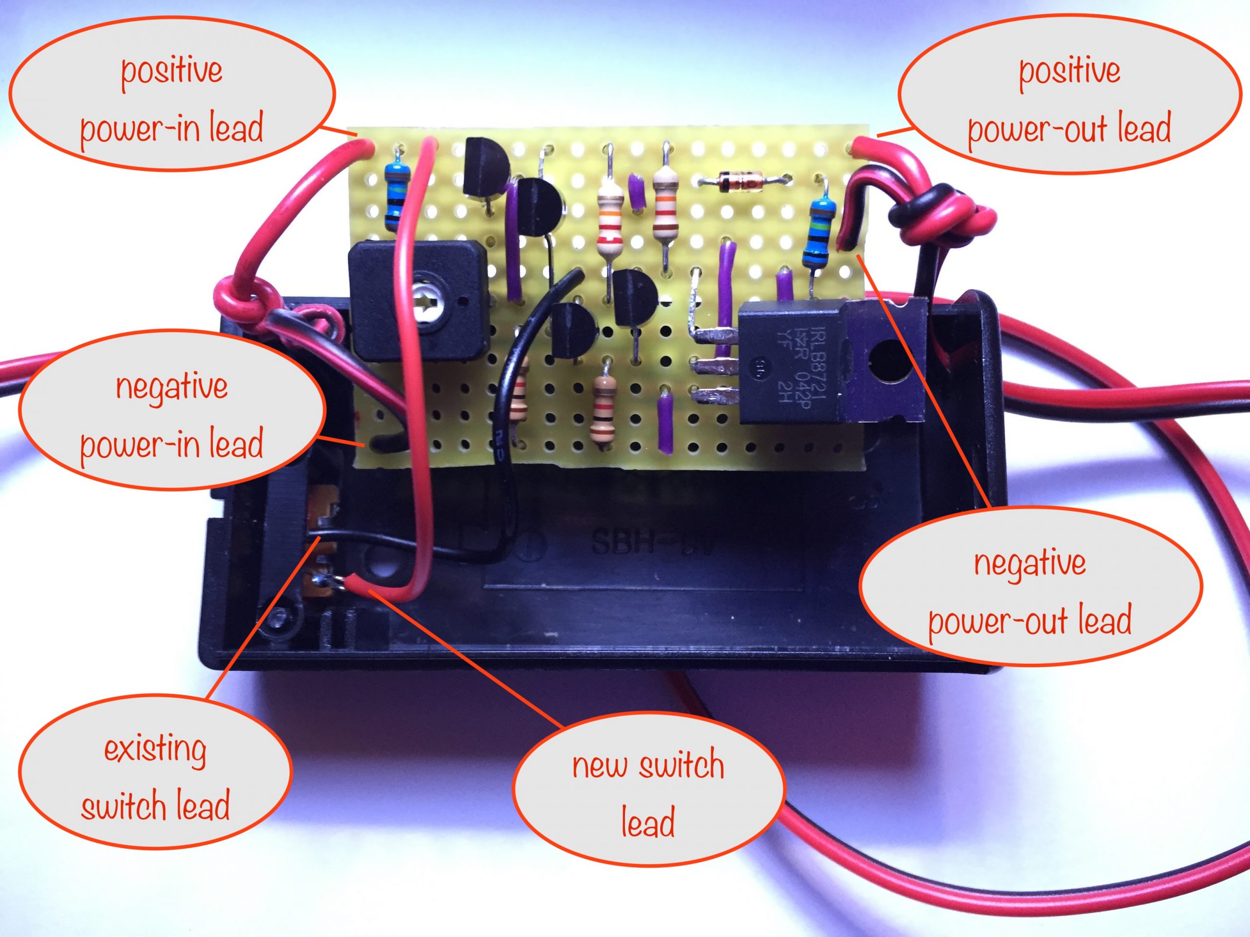
Soldering the leads
It’s time now to solder the power-in and power-out leads to the stripboard; same for the battery-box switch.
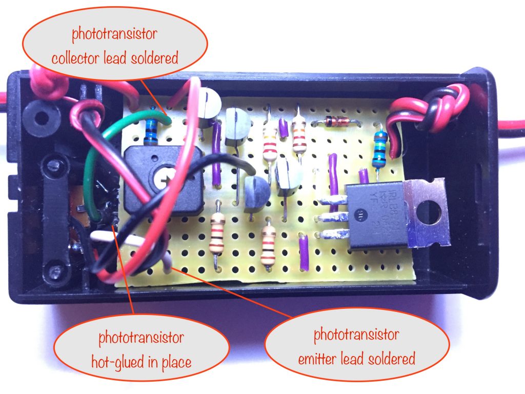
Preparing and soldering the phototransistor
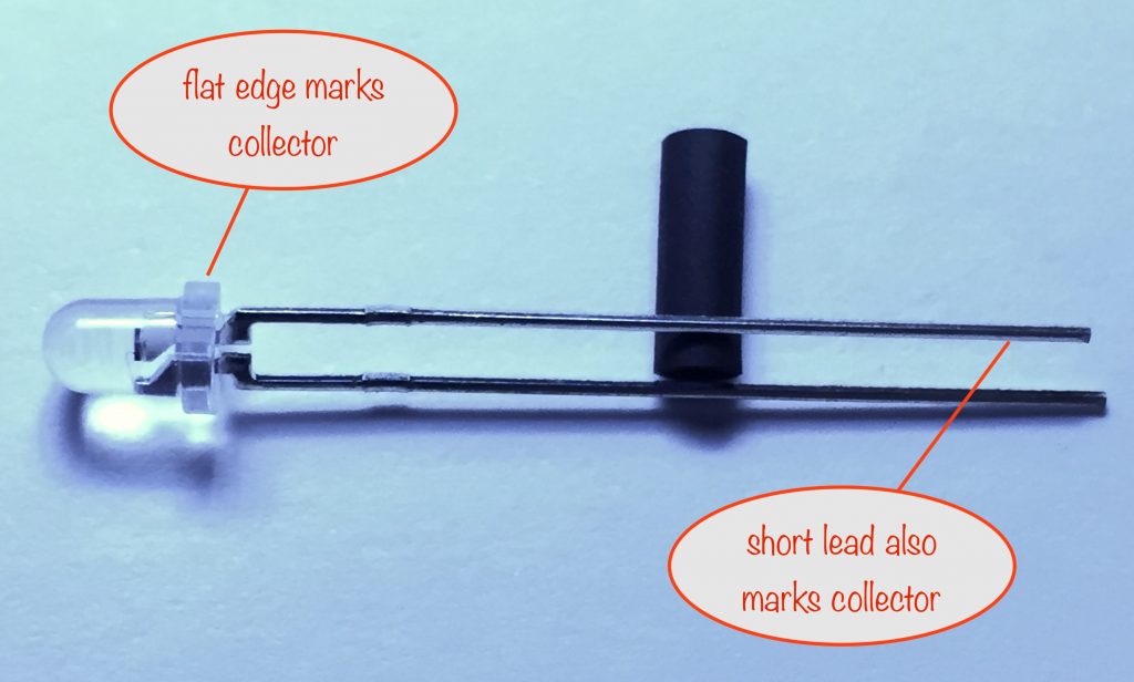
photo of phototransistor, identifying the flat edge / collector
Use your wire strippers to strip 3 or 4mm off the ends of two different coloured wires. Form them into small circles so they’ll fit around the legs of the phototransistor.
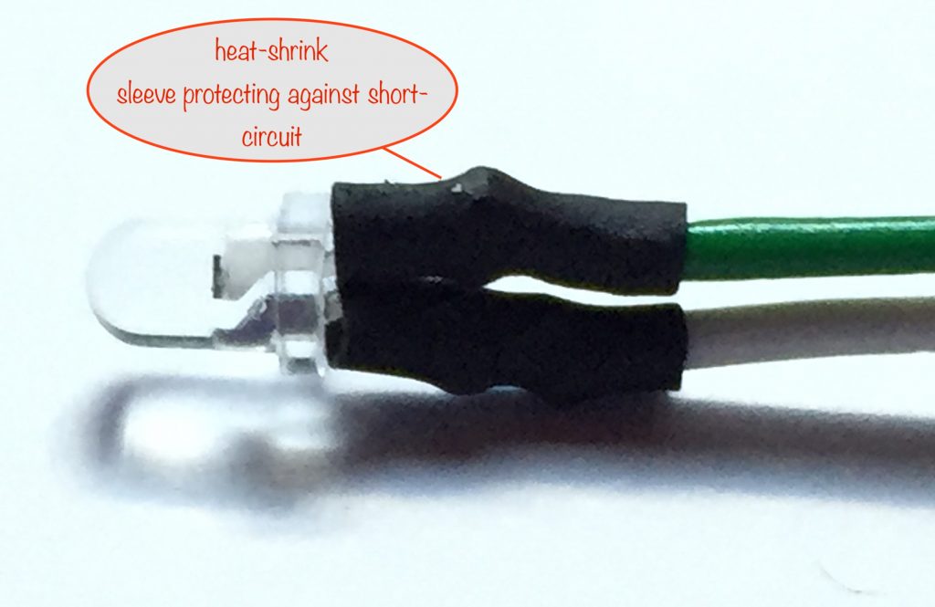
Solder a wire to one of the legs of the phototransistor near its body, clip off the excess leg and slip a piece of heat-shrink sleeve over it. Do the same for the other wire and leg.
You can use the barrel of your soldering iron to shrink the sleeving, as long as you’re gentle with it. You don’t need to leave it on for long at all.
Make note of the colour you attach to the collector (the shorter leg, the one closest to the flat edge). This is so you don’t get mixed up when soldering the other ends to the stripboard.
Note that this is the other way round to LEDs where their flat edge marks the leg that gets connected more negatively. The phototransistor instead has the flat edge marking the leg that gets connected to the more positive end of the circuit.
I’m using green (collector) and white (emitter).
Next you’re going to put the phototransistor into place and hot-glue it into place. Once you’ve done that, you can solder the wires into their respective holes on the stripboard.
Testing your dark-activated switch
Now it’s time to test your dark-activated switch circuit and make sure you can set a darkness switch-on point.
- connect the test LED (with a 220Ω or thereabouts current-limiting resistor in series) to the output / load wires. Make sure you get the polarity right – the LED’s long leg should connect to positive (or the current-limiting resister should, if you chose to solder it to the long leg)
- make sure the battery box switch is in the ON position (meaning that the light level is ignored and the LED should be permanently on)
- hook up power to the input leads. For testing, 3 NiMH batteries in series will give around 4 volts and will do just fine.
The LED should now be on. If it isn’t, make sure the LED works, you’ve got the polarity right and the battery box switch is in the ON position.
If all thats ok, then check your stripboard connections – the battery box switch when ON takes the gate of the MOSFET high, overriding the rest of the circuit and forcing it to switch on. So make sure those connections are fine and doing as they should.
Set a darkness switch-on point
Assuming the LED does come on with the battery box switch in the ON position, switch it off. Having done that you can now use the trim pot to set when the LED comes on.
For a later (darker) switch-on, you turn the trim pot clockwise. If you want it to come on when there’s more light, turn it anti-clockwise.
When testing the trim pot setting, you need to be aware that the phototransistor is very sensitive and is affected by light coming in at its top and at the bottom where its legs go in.
Even with the battery box lid on, some light will still leak in through the holes where the power-in and -out leads go, where the switch slider is and through the tiny hole under and to the right of the switch (twin to the one you enlarged to seat the phototransistor).
So if you’re trying to shield the phototransistor from light, take that into account.
Start with the trim pot turned fully anticlockwise. Unless you’re on the equator, outside at noon on a cloudless day, the LED should be on.
Now turn the trim pot slowly clockwise until the LED goes off. You’ve now set the current light level as the switch-off point. If it gets slightly darker, the LED will turn on.
If you’re indoors in a room without any natural light, you can turn off the lights and the LED should come on. Otherwise you’ll need to shield the phototransistor from the light in some other way.
Assuming all works as intended, you can close up the battery box and wait for dusk to check the darkness switch-on point, adjusting the trim pot again if necessary.
Note that you won’t be able to set a darkness switch-off point between very low light levels and very, very low light levels
Next steps
If you’re going to power the dark-activated switch from a mains adapter (wall wart) then I’d highly recommend using its matching connector on your power-in leads. This will usually be an inline 2.1mm female barrel connector ![]()
For this to be modular and usable with the LED display modules, you’ll need to fit connectors to the load leads that match the connectors on the LED display modules in the other projects of this series.
Making them modular gives you maximum flexibility in setting up and changing things around for different circumstances (Christmas decorations, parties, relaxation room, night lights…) Of course, you could just solder the leads from a dark-activated switch to your preferred LED display module or you could use spring wire connectors – it’s up to you.
I prefer something more solid and, because they’re quite cheap (and also because I had plenty to hand), I’m using EC5 connectors ![]() . If you want to go a similar route, I’d suggest using EC2 connectors instead (a smaller version, just as good).
. If you want to go a similar route, I’d suggest using EC2 connectors instead (a smaller version, just as good).
There’s a knack to attaching them to your leads – YouTube has a few how-to videos on soldering the EC range of connectors.
Whichever way you go, enjoy the fruits of your labour! 😎
Other projects in the Nifty Hobby Projects for LEDs and Solar series (so far, more to come very soon):
- Flasher Memory Aid
- 5 LED String
- Fibre Optic Display
- Mini Sparkles Colour-changing LED Fibre Optic String
- Solar Lithium Ion Battery Charger
- Solar NiMH Battery Charger for 2 AAA batteries
- Solar NiMH Battery Charger for 2 AA batteries
- Solar NiMH Battery Charger for 6 AA batteries
- Timer-delay Off Switch
- 4-LED Porch Light
- 10-LED Bedside lamp
- Mini Camping / Bedtime Reading Lamp
- Main page with links to where to buy stuff