the Memory Aid LED Flasher is a stand-alone module in the Nifty Hobby Projects for LEDs and Solar series
LED = Light Emitting Diode
If you’ve stumbled into this page and you’re not interested in making one as a project but want to buy one ready-made, order yours at this link.
This project actually came about for my own use. After a shower, I’d turn on the extractor fan and then get on with things – only to realize a few hours later that I’d forgotten to switch it off!
This is a really great project for kids either approaching or already into their teens. No electronics knowledge is needed as everything is explained. Obviously care must be taken when working with a soldering iron – so be warned!
I was looking for a cheap solution to this repeated failing that didn’t include rewiring the extractor fan with a timer.
Now, my shower is just off the kitchen and I’m always in and out, making cups of tea etc. So I came up with the idea of having a flashing LED that would be so obvious when I went to the kitchen that I couldn’t help but see it.
Problem solved!
..and one thing LED to another
(LED to another – geddit? hehe!)
I then realised that such a device could have a much wider application. You see, my mum’s memory is starting to fail her and she’s told me that on a few occasions she’s forgotten about something she’s cooking and has ended up burning it.
The flash reminder to the rescue!
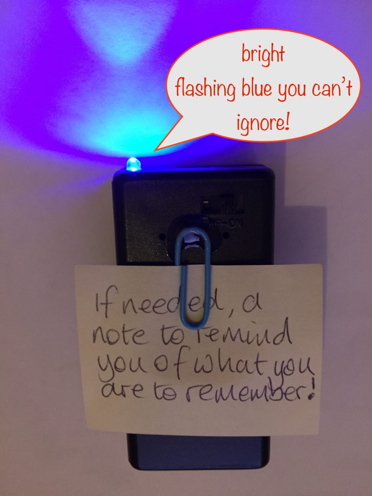
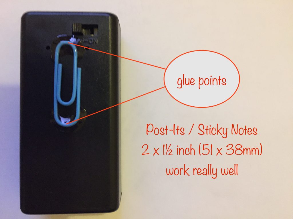
To make my orginal design even more helpful, I glued on a paper clip so you can easily attach reminder notes – those small 38 x 51mm Post-Its are perfect for it.
How and when do you use it?
Make sure you keep it in your line-of-sight when you’re sat down in your usual chair. That way, you’ll always see it when it’s switched on.
The sorts of things it’s useful for:
- Just put something in the oven or on the stove? Switch on the flasher. If it helps, write down when the cooking should be done and attach the note to the flasher’s paperclip.
- Need to post a letter when you go to the shops? Write a reminder and attach to the flasher’s paperclip. On the day, switch on the flasher so you don’t forget to check your reminders.
- Have you just realised you need to buy something on your next visit to the shops? Write yourself a reminder note and slip into the flasher’s paperclip.
- Did you make a phone call and find out you have to call back later? Write a note about it, slip into the flasher’s paperclip and switch it on.
- Did you just remember it’s someone’s birthday and you have to write a card? Make a note and put in the flasher’s paperclip.
How long will the battery last?
If it’s switched on for 2 hours per day, a standard (ie Zinc) 9v PP3 battery will last around 60 days. An alkaline battery will last for around 90 days.
When the flashes become noticably dimmer, then it’s time to change the battery.
Making your Memory Aid LED Flasher
Parts list:
- 1 x PP3 battery holder with in-built switch
- 1 x PP3 Zinc battery – or Alkaline for longer life
- 1 x 3mm flashing blue LED
- 1 x 1/4 Watt 220 ohm resistor to limit the current through the LED
- 1 x paperclip
Tools etc. you’ll need:
- 18 Watt soldering iron, 25 Watts at a push
- Desoldering pump / solder wick – in case of mistakes!
- “Helping Hand”
 – invaluable aid while soldering or gluing
 - Wire strippers covering 26 to 16 AWG
- Side cutters
- Small snipe-nose / needle-nose pliers
- Set of watchmaker-style screwdrivers (cross and flat-bladed) – for poking, prodding and levering the LED into place
- Glue gun for insulating components and wires and fixing everything in place
- UV-glue for fixing the LED in place (optional) and gluing the paperclip to the front
Preparing the battery holder
There are two types of PP3 battery holders commonly available that are ideal for this project:
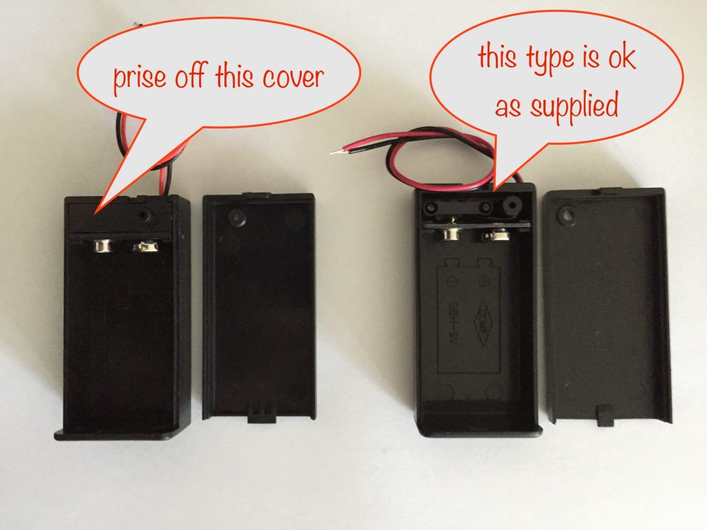
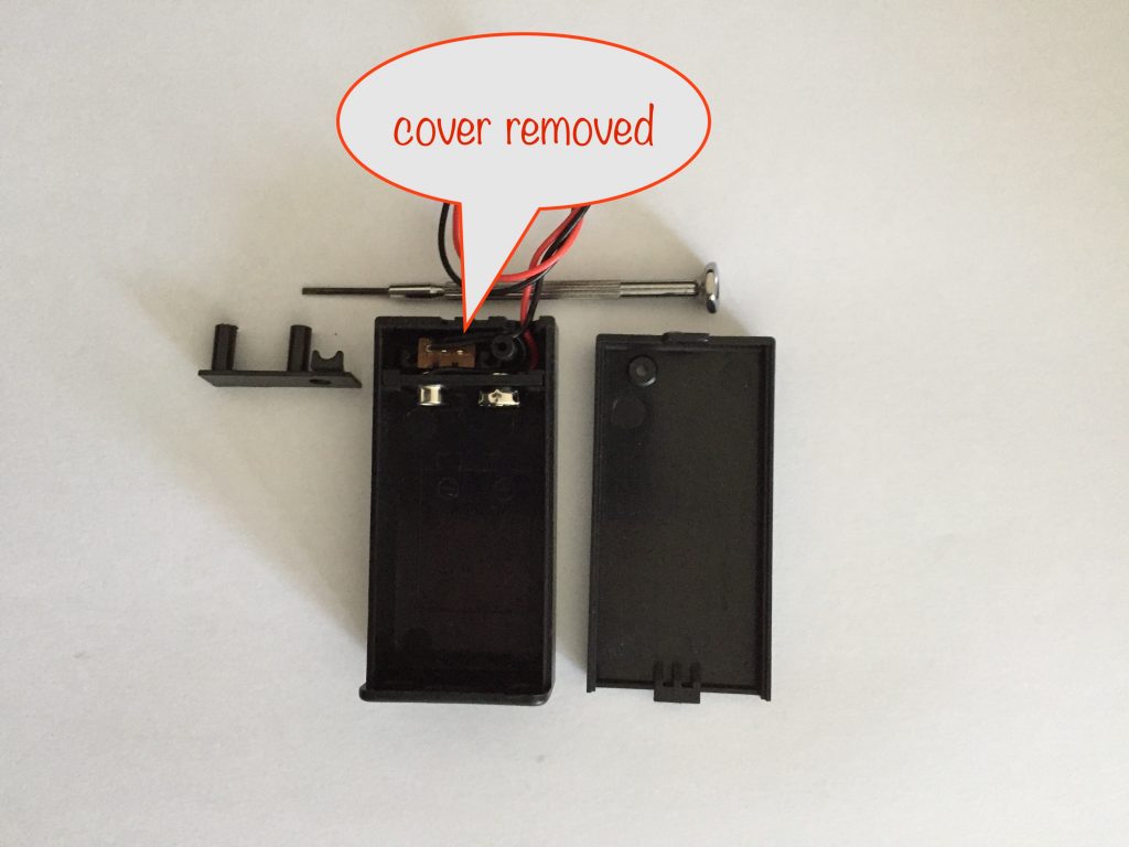
If you have the type on the left, carefully prise off the cover with a small watchmaker-style flat-bladed screwdriver to reveal the switch and wires. You can then dispose of it as it’s of no further use. With this type you’ll need to secure the switch in place using hot glue – done in the second-to-last step
Whichever type you have, you now have to pull the wires out of the hole and back into the box. Push them through the hole until you can grab them and pull the rest of the way.
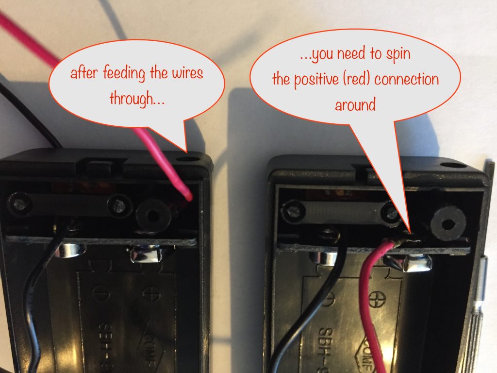
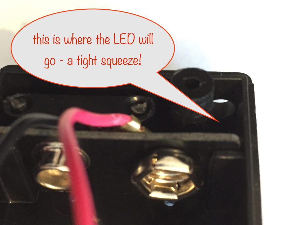
The next step is to spin the positive connector so the red lead is out of the way, clearing the space where the LED will go. I use a screwdriver to lever the crimped connector. It’s a bit fiddly and you might need to be a tad more than gentle!
Preparing connections and soldering
Steps:
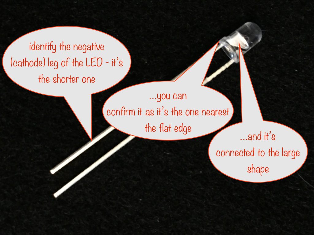
- Identify the negative leg of the LED
- Bend the negative and positive legs to shape
- Jiggle, coax and cuss the LED into place
- Form the 220 ohm resistor lead and slip over the negative LED leg
- Cut, strip, tin and form the negative (black) wire around the other resistor lead
- Solder the resistor connections
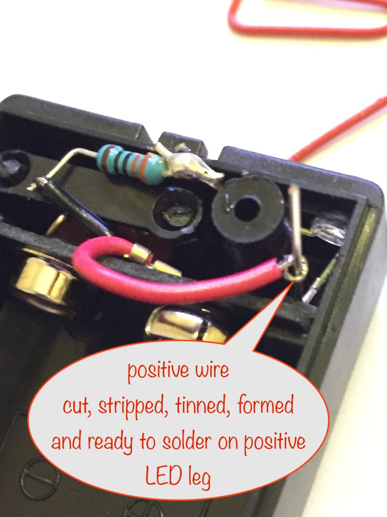
- Cut, strip, tin and form the positive (red) wire around the positive leg of the LED
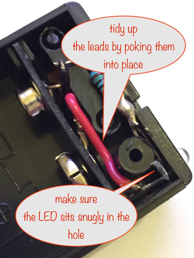
- Solder the positive wire, clip off the excess leg and tidy the wires
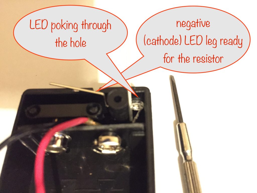
Identify the negative leg of the LED
This is important so make sure you get it right!
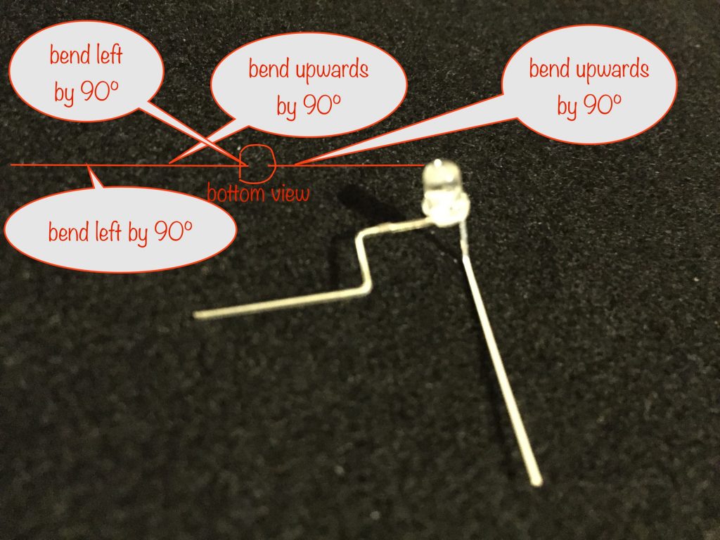
Bend the negative and positive legs to shape
This isn’t so easy to show in a photograph but hopefully the diagram helps. Also have a look at the photographs underneath it and it should make more sense.
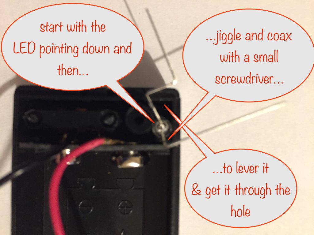
Jiggle, coax and cuss the LED into place
Start off with the LED pointing down and then gently lever it with a screwdriver so it pokes through the hole (the one that the wires originally went through).
Be careful not to distort the bends you made in the legs of the LED – if you do, do9n’t worry too much as you’ll be able to bend them back into shape after you get the LED poking through the hole.
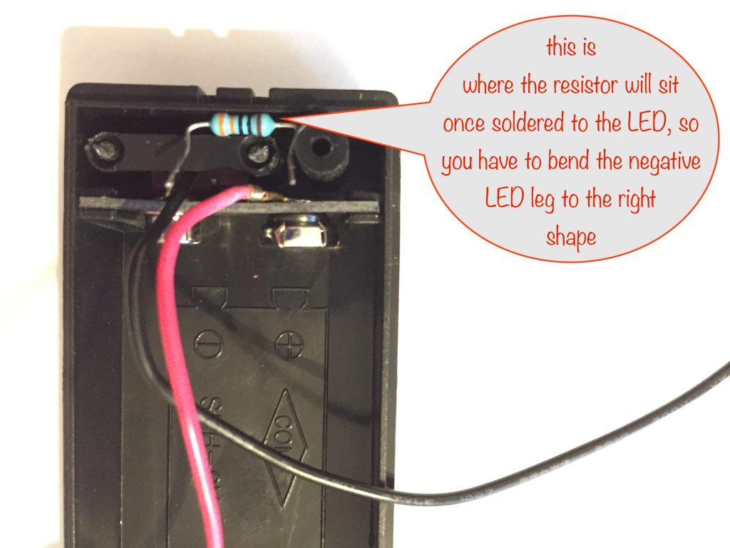
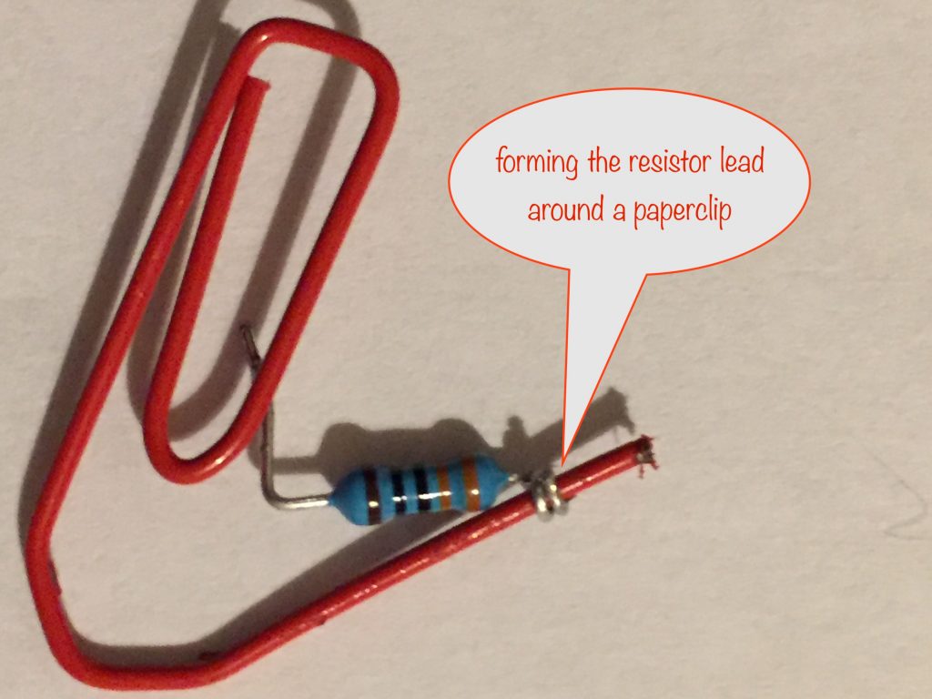
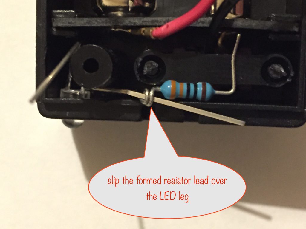
Form the 220 ohm resistor lead and slip over the negative LED leg
I use a paperclip to do the forming. The ones I’ve got are slightly thicker than the component leads so it works well.
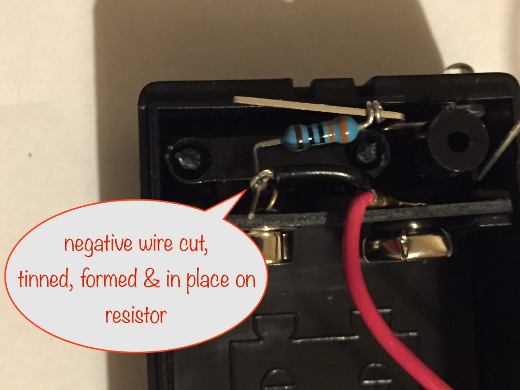
Cut, strip, tin and form the negative (black) wire around the other resistor lead
Now prepare the negative wire. Cut it to length and strip it. Then tin it and form it so it slips over the other end of the resistor.
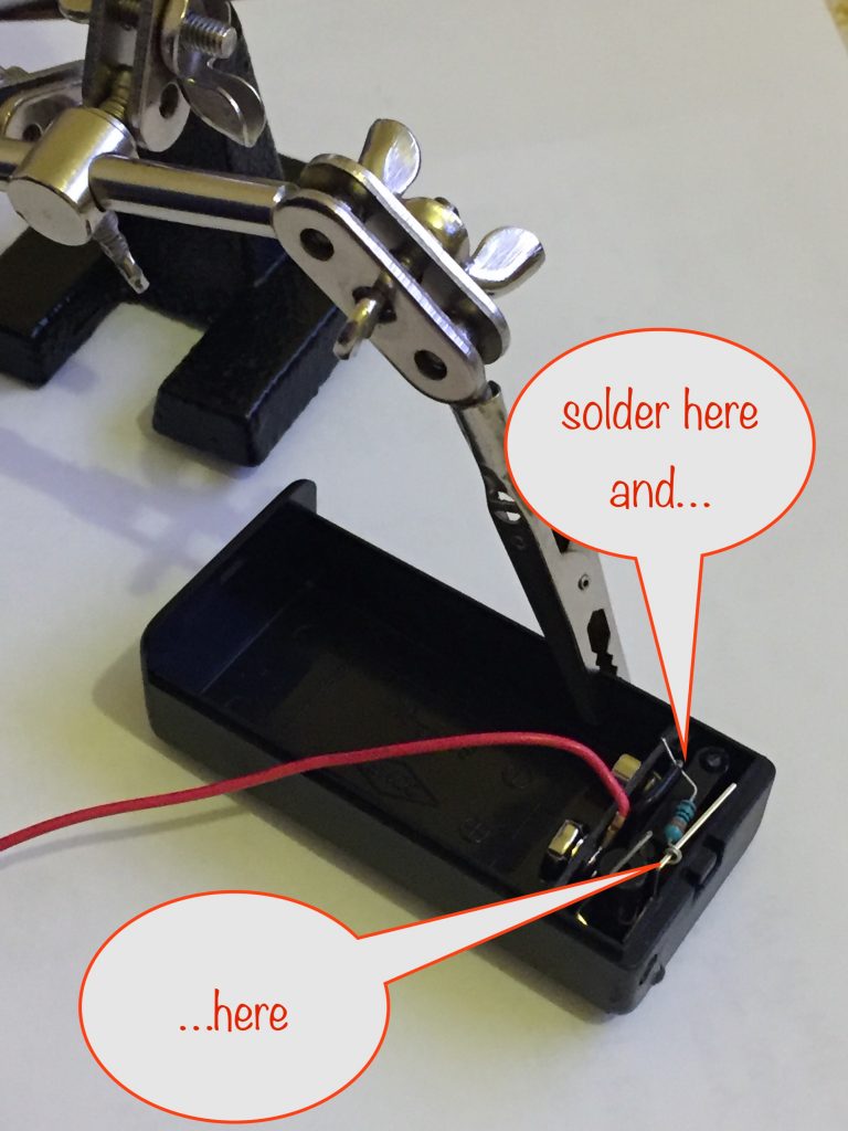
Solder the resistor connections
Plug in your soldering iron and, after it’s warmed up, give it a good clean. Use your “Helping Hand” to steady things ready for soldering. Apply a little solder to the end of your iron and you’re ready to go.
Cut, strip, tin and form the positive (red) wire around the positive leg of the LED
Now it’s time to solder the positive lead to the positive leg of the LED. Once you’ve prepared the wire and slipped it over the leg, push it down so it’ll be out of the way once soldered.
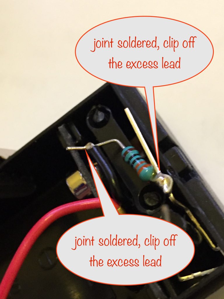
Solder the positive wire, clip off the excess leg and tidy the wires
Testing and finishing off
Steps:
- Make sure it works before continuing!
- UV glue and / or glue stick everything in place
- Last step: UV-glue a paperclip to the front
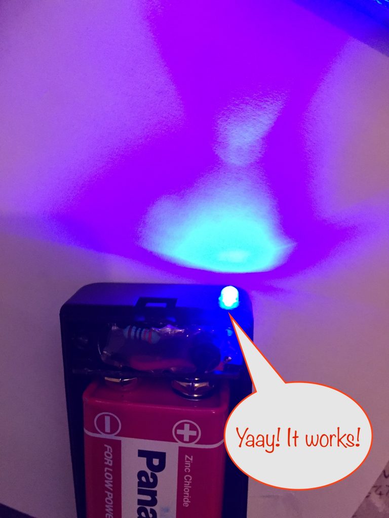
Make sure it works before continuing!
Attach a battery and slide the switch on. Your LED should now flash.
If yours doesn’t work, check your soldering.If that seems good, are you sure you correctly identified the positive and negative legs of the LED?
You can quickly check if this is the problem by turning the battery over and holding it against the connectors. Doing this will reverse the polarity and if it now flashes, you need to correct things. One way is to cut the positive and negative wires, add a short length to each and then swap them over – black to red and red to black. That might be easier than redoing things from the start!
UV glue and / or glue stick everything in place
Assuming all is well, it’s now time to make sure everything stays in place. I prefer to use UV-glue to hold the LED in place and then use a glue gun to insulate and lock everything else in place.
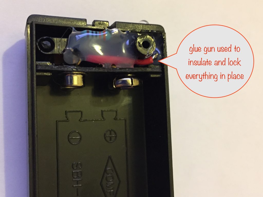
If you used the other type of battery box, make sure you securely fix the switch in place by smothering with hot glue.
Last step: UV-glue a paperclip to the front
To easily attach a note to your flasher so the reminder doesn’t get lost, use UV-glue to fix a paperclip to the front. Don’t use superglue – it’ll stain the black plastic with ugly white streaks.
Other projects in the Nifty Hobby Projects for LEDs and Solar series (so far, more to come very soon):
- Dark-activated Switch
- 5 LED String
- Fibre Optic Display
- Mini Sparkles Colour-changing LED Fibre Optic String
- Solar Lithium Ion Battery Charger
- Solar NiMH Battery Charger for 2 AAA batteries
- Solar NiMH Battery Charger for 2 AA batteries
- Solar NiMH Battery Charger for 6 AA batteries
- Timer-delay Off Switch
- 4-LED Porch Light
- 10-LED Bedside lamp
- Mini Camping / Bedtime Reading Lamp
- Main page with links to where to buy stuff