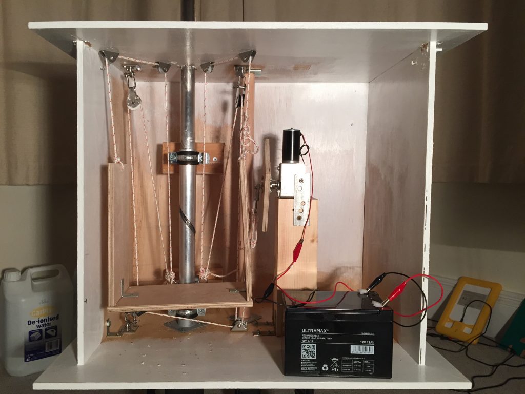
The scaled-up solar tracker has been working really well since I installed it in the early autumn. Now that winter is approaching a quick check showed that there are some things to sort out:
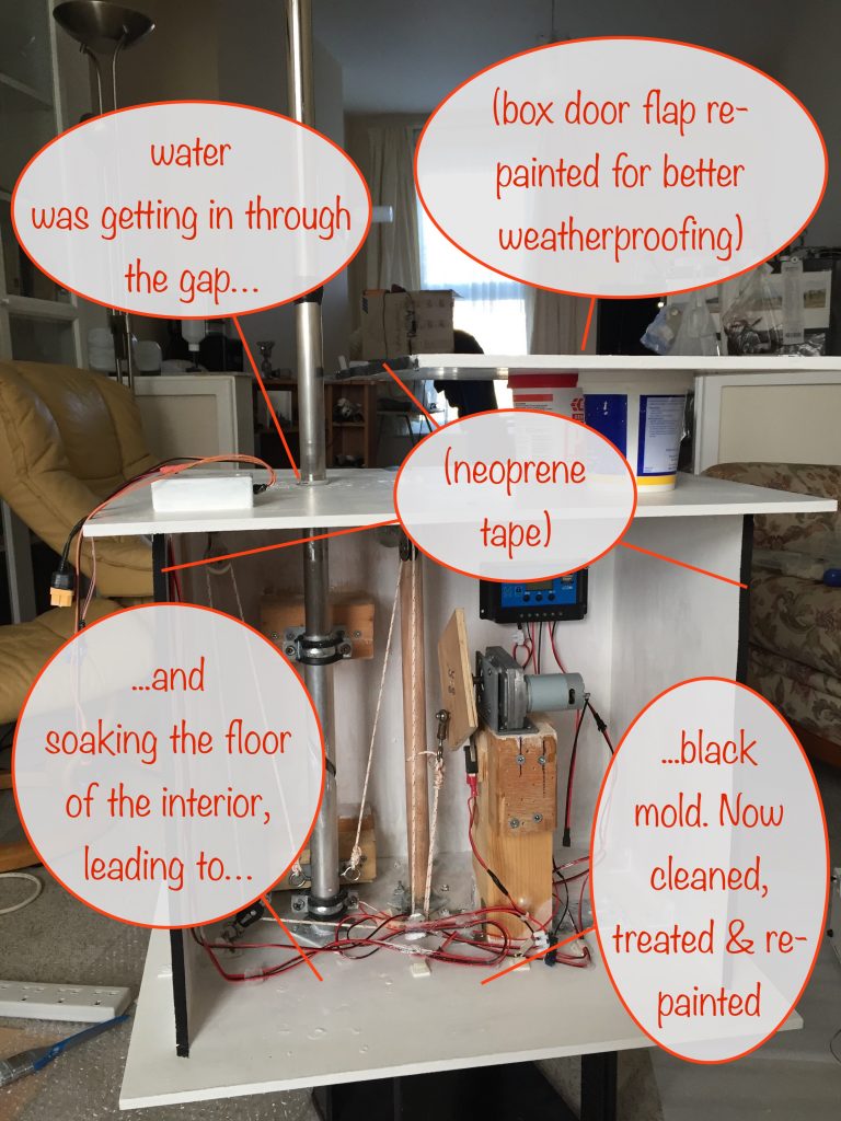
- black mold growing on the bottom of the interior of the box – caused by…
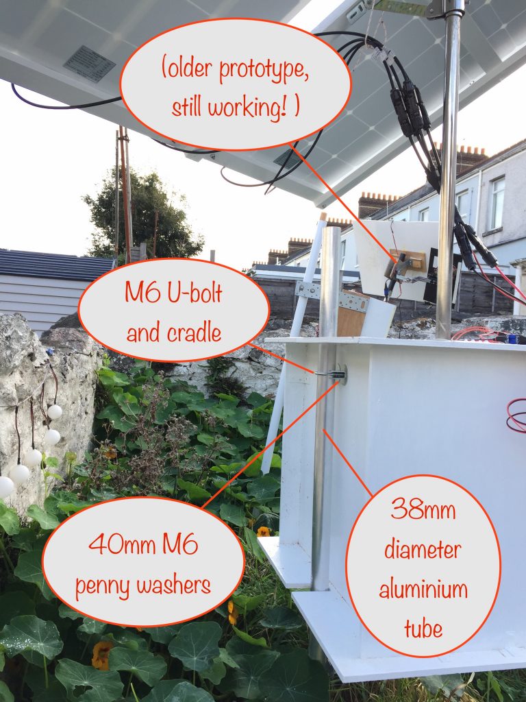
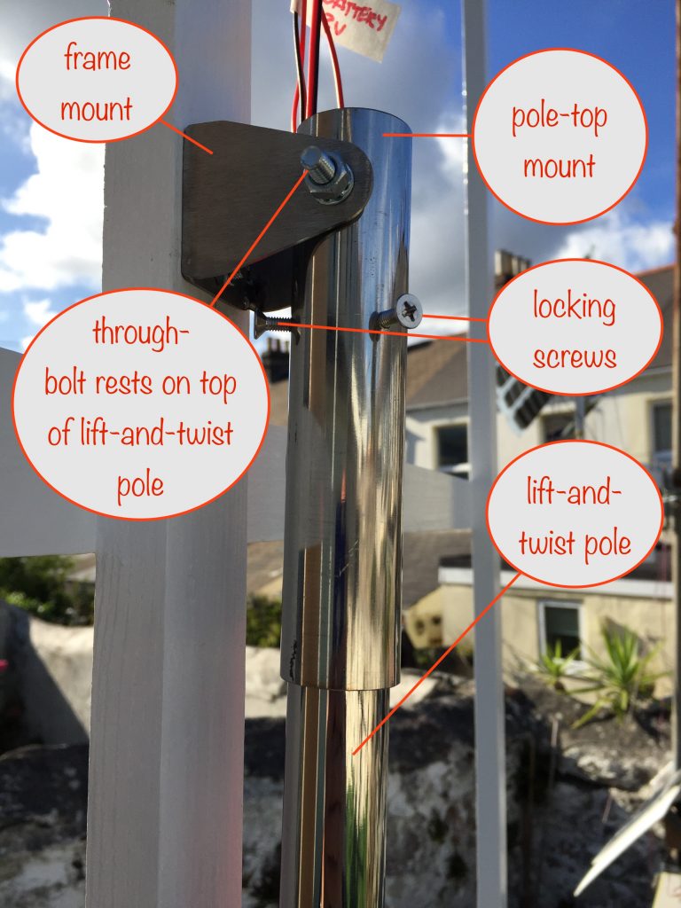
- ..water getting into it via the hole for the lift-and-twist tube
- the edges of the slot in the aluminium tube was damaged by the screw holding the guide pin. It came loose and, being in contact with the edges, it chewed them up some
So I needed a way of:
- killing the black mold
- stopping the water getting in
- finding a better way of anchoring the guide pin
The first thing I did was to bring it indoors and remove some surface paint so that the partially water-logged wood could dry out. I gave it 4 or 5 days, checking daily with a multimeter on the ohms setting. Around the hole, it started out at around 5MΩ and, after drying out, raised to well over 100MΩ – good enough.
Killing the black mold
I used some specific black mold remover / preventer that I already had for treating it in bathrooms etc. I couldn’t use bleach as it only kills surface mold when it’s on wood.
After 48 hours drying time I repainted with 2 coats of undercoat and 2 topcoats.
Stopping the water getting in
I already had neoprene sealing strips around the flap used to close off the box at the front and they were working just fine.
The problem was where the lift-and-twist tube entered the top of the box.
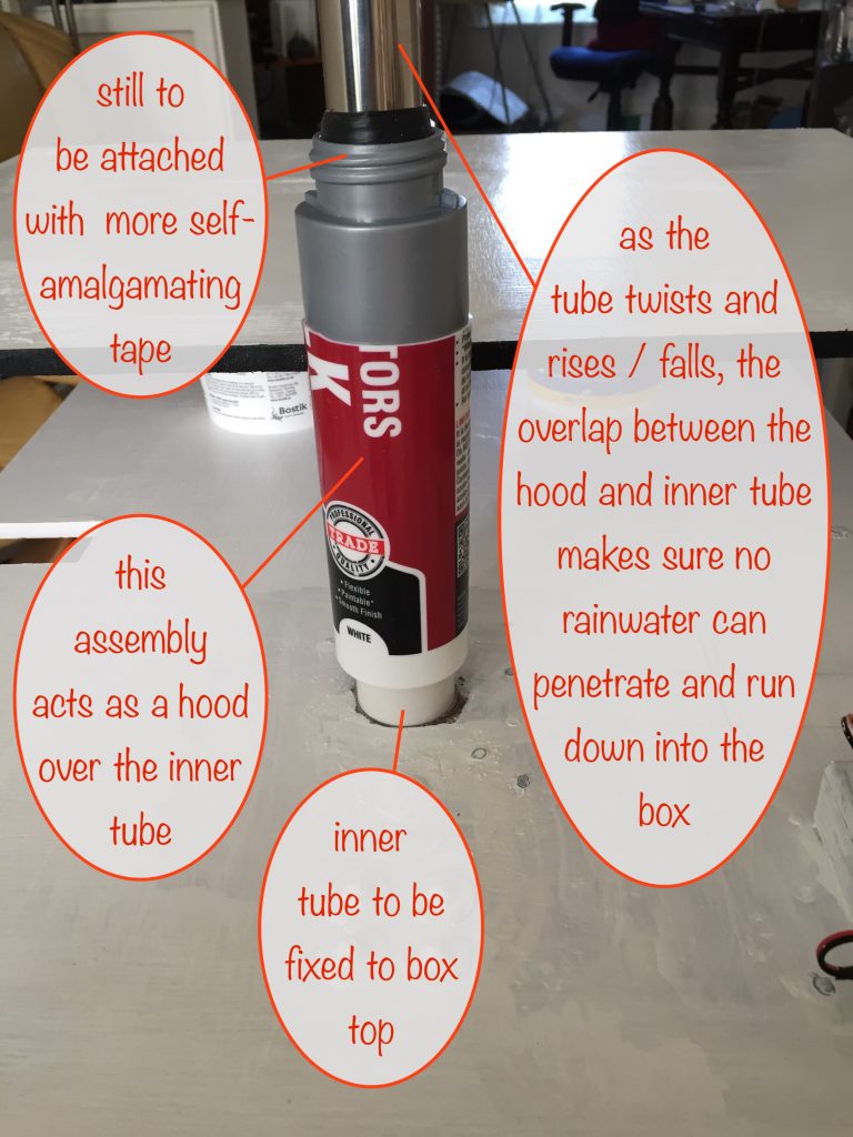
After much head-scratching, I came up with a solution: a hood attached to the lift-and-twist tube that overlaps a tube connected to the box top. And done in such a way so that the lower part of the lift-and-twist tube is never directly exposed to the elements.
Parts
I happened to have these to hand and luckily it came together as planned:
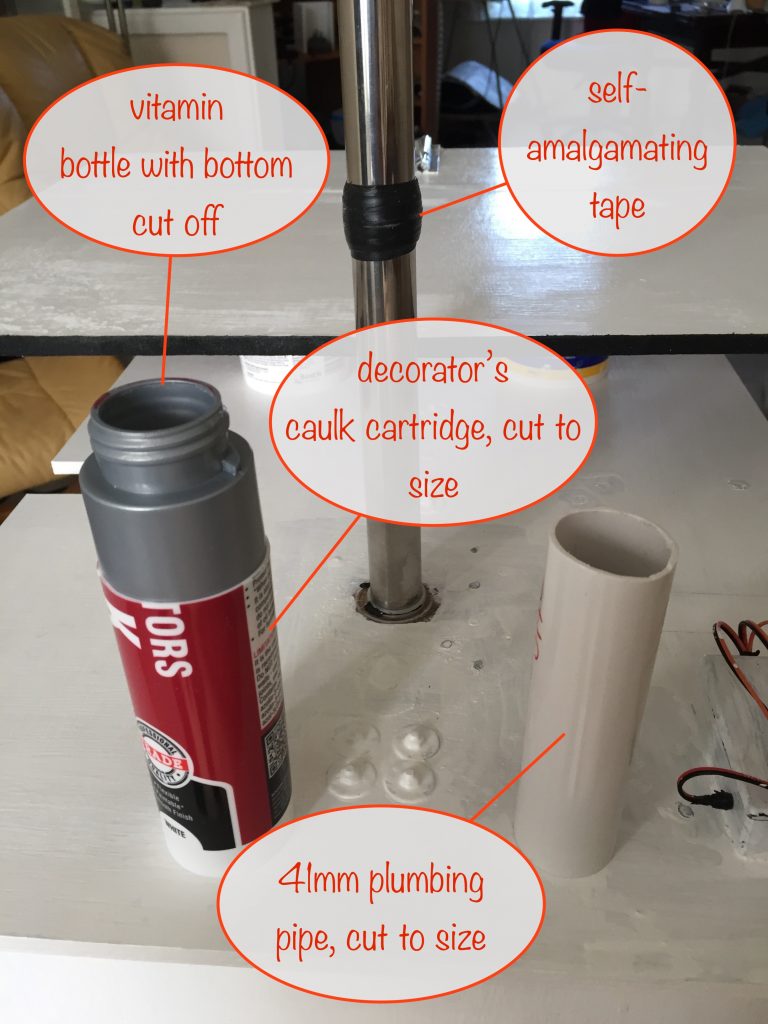
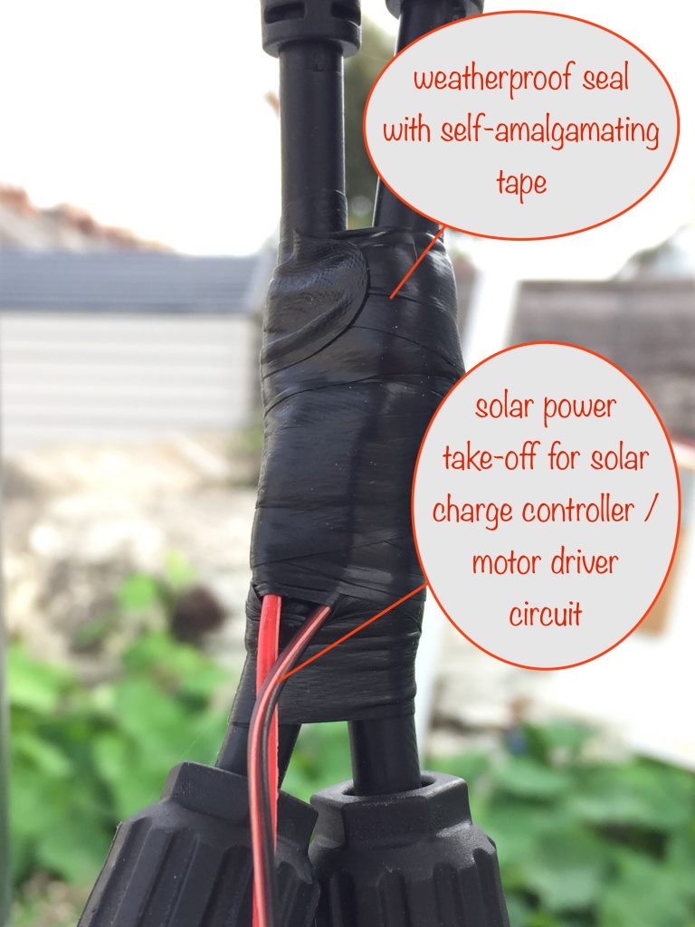
That self-amalgamating tape is a life-saver, useful in so many ways.
If you’ve not used it before, it’s not sticky but when you stretch it to around half it’s width or less, it ‘activates’ and will stick to itself. After around 10 minutes or so it starts to form a solid mass and after a few hours the process is complete.
Partially assembled
Here I’ve put everything in place to make sure it works as intended before fixing things to each other.
With that done, onwards with the final assembly…
Fully assembled
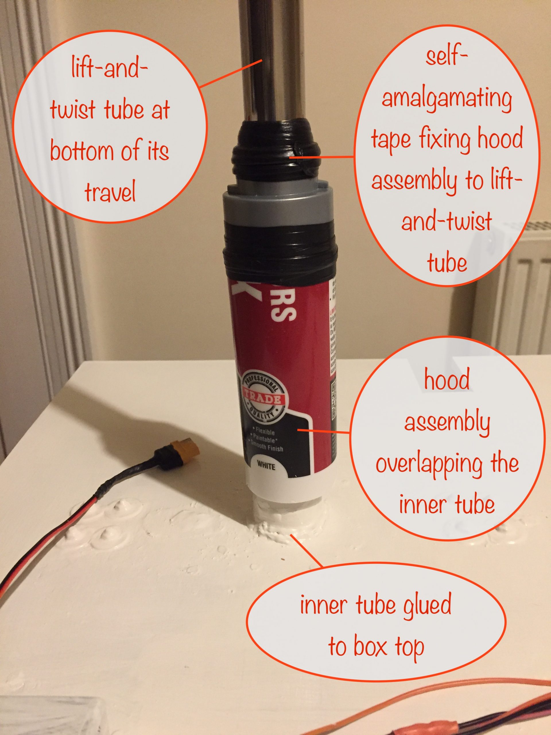

(click for larger image in a new tab / window)
I used black hot glue to fix the inner tube to the top of the box. The black hot glue sticks have a slightly higher melting point and seem to hold plastic better than the white or clear versions.
Even so, to protect it from the UV radiation that tends to break it down, I painted it with undercoat and a couple of top coats of white gloss.
Next I used more self-amalgamating tape to seal the join between the vitamin bottle (with the bottom cut off) and the cut-to-size caulk cartridge. That’s what I’m calling the hood. Finally I used the tape to attach the hood to the lift-and-twist tube as shown.
Anchoring the guide pin
The main problem was that the screw holding the guide pin only had 3mm of thread to screw into – that’s the wall thickness of the stainless steel lift-and-twist tube – and easily worked itself loose.
Again, more head-scratching and cogitating and then the solution came to me…
I took a length of wooden dowling that fitted nicely inside the lift-and-twist tube and was long enough to reach the bottom. I drilled out the threads on the tube and used a self tapping screw so it would fix firmly into the wood, through the hollow guide pin.
With the solution proved, I gently filed away where the slot edges had been chewed up some and then finished off with some wet-and-dry for the final smoothing.
Perfect 😎
Finishing off
The final step was to give the whole thing a couple more coats of gloss and that’s the winter maintenance complete.
I’ll be putting it back outside again in the spring – towards the end of February because that’s when the sun will be high enough in the sky to start reaching down into my back garden. I just need to find somewhere to store it until then!
I suppose I could put it outside….