In this post:
- working with the new motor
- I still got the torque wrong – I stupidly ignored friction
- Introducing the counterweight concept to make up for it
So the motor arrived
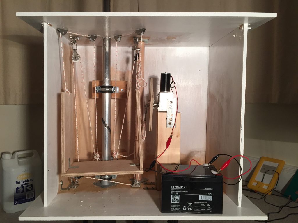
I got quite excited! I had to get a block of wood cut to mount it on and a quick trip to my local supplier got that sorted.
I mounted the motor and gave it a quick try on progressively heavier loads tied onto the lift-and-twist pole.
It was nowhere near able to lift the required weight due to frictional losses. Alas, alack, woe is me! And then I realized I’d been stupid (again!)
Counterweight Cradle
From the outset, all the design needed was a counterweight so that the motor wouldn’t have to lift the whole lot by itself.
So a quick rejig and I had a cradle mounted via pulleys to take the counter weight. I attached its cords to the lifting eyelets at the same place as the motor cords are attached. I’ve made a short video (25s) without any loads so you can see it in operation:
Note that as the counterweight cradle goes down, the pole twists and goes up, driven by the motor. When the cradle goes up, it’s the weight of the pole going down that lifts it, as the motor relaxes its pull on the cords.
Counterweight in action
Here’s a video (58s) showing how it works under realistic loading:
- Weight on pole: 12.5kg
I’ve used containers filled with water and tied them to the pole as a substitute for the frame (3.5kg), top mount (1kg) and two flexible solar panels (6.2kg) – with a little extra as a fiddle factor - Counterweight: 6.5kg
For the counterweight I’m temporarily using the 12V battery that drives the motor and a lump of rock – it’s actually half a polished stalactite I picked up on a dig of a collapsed passage from my caving days, but that’s another story… - Frictional losses on motor lifting path: 6kg
These losses mean that the maximum lifting power of the motor (around 13kg at 45mm from the shaft as used here) is almost reached with the above loadings
Observations
- As the weight on the pole increases, so the counterbalance weight has to be increased to help take the strain from the motor
- Uh oh! As the weight on the pole and the cradle increases, so do the frictional losses
- There’s a limit imposed by this beyond which the motor can’t supply enough power to lift the pole and the weight on it.
- Increasing the counterbalance weight when this happens (to assist the motor’s lifting force and so be able to lift the pole and its weights) means that the combined weight of the pole and the weights on it aren’t enough to allow the pole to drop down when the motor relaxes its lift – the counterbalance weight together with the frictional losses are just too great to allow the pole to drop
- Luckily this happens at a (slightly!) greater weight than the combined weight of the pole, the pole-top mount, the frame and the solar panels
- The motor I’ve used has a small amount of backlash (Wikipedia definition)
- When the cord that’s attached to the rod end bearing on the motor plate goes over the top, there’s a clunk as the backlash kicks in.
- Without the counterweight and with a more powerful motor, I’d be concerned that the repeated shock it would give the motor’s gears might eventually lead to gearbox failure
- If I was starting the build again from scratch, I’d use a different approach to the lifting:
- I’d use a linear actuator (Wikipedia definition) with a similar or slightly better torque rating
- It would need a double pole double throw switch / relay so that when the top of travel is reached, the actuator motor’s positive / negative could be reversed to bring the pole down again (drop and reverse twist)
- A similar arrangement would be needed for when the pole reaches the bottom of its travel, swapping the actuator motor’s positive and negative again so it would lift the pole once more.
- (it would still need another switch to cut power entirely when things have returned to their dawn starting position at dusk)
- The cost of the linear actuator and switches / relays would come out about the same as the current motor and pulleys I’ve used.
- It would also give a simpler build and one that could easily be scaled up even further to lift more than the two solar panels
Next steps
I’m waiting for the pole top mount to be made by a local supplier. As soon as it arrives I’ll fix it to the frame and then mount it on the pole.
I’ll still need to attach a couple of containers filled with water (6.2kg) to the pole to act as a substitue for the solar panels. I’m not ordering them until I’ve proved everything – just in case!
Upwards and onwards 😎