(click for large image in new tab / window)
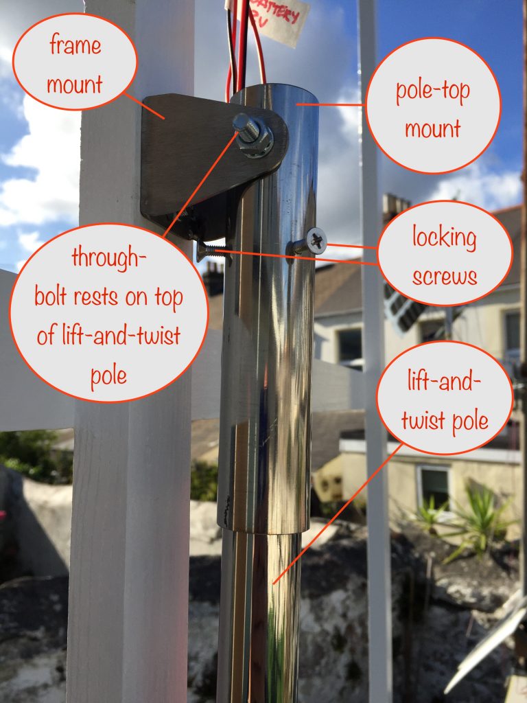
Pole-top Mount arrived
Well.. most of it. I’m still waiting for the clamp that will let me angle the solar panel frame to point higher in the sky in summer and lower in winter.
The clamp will go around the bottom of the pole-top mount tube and be connected to the frame via a tie and slotted bracket. That way the angle of the frame and solar panels can be adjusted as the year progresses.
Motor driver circuit – actual
In the previous circuit I emulated the sensor solar cells and the motor. I’ve now fitted them so I’ve got a working prototype.
Here’s the circuit now:
(click for large image in new tab / window)
Wiring it up
While waiting for the pole-top mount to be completed, I made it easy to connect and disconnect the wires from the motor-driver circuit, housed near the top of the frame, to the parts in the main box:
- 12V battery
- Motor
- Microswitch
The microswitch is on the output of Comparator-2 and, at dusk, stops the motor when the solar panels have reset to their dawn start position. It’s mounted on the wooden block holding the motor and is activated by the bolt the rod end bearing is attached to.
I used EC5 connectors for the 12V supply from the battery and half an EC3 connector for the power to the motor from the MOSFET’s drain.
I then routed and hot glued the wires in place inside the main box.
First run
I transported everything into my back yard, put the pole-top mount and frame in place and plugged the various connectors together.
I connected the 12V battery first and used my multimeter to double check that all was good in the motor driver circuit.
With that showing ok, I plugged the rest of the connectors together – no smoke or flames – always a good sign, hehe!
Weighting
I weighted the lift-and-twist pole with containers of water as a stand-in for the solar panels.
Next I filled the counterweight cradle with a house brick and just enough small pebbles so that the motor was able to lift the pole – but not so much that it prevented the pole from dropping again when the motor had rotated past the half-way point.
The run…
Luckily the day turned out sunny with the odd cloud or two. This meant I was able to do the fine tuning to get the sensor solar cells to work as intended.
All I had to do was to adjust the trimpot so that when the main sensor solar cell was in direct sunlight the combined sensor solar cells’ voltage was only just enough to switch on power to the motor.
Finally, when it turned to dusk and there wasn’t enough light to keep the sensor solar cells above the lower voltage threshold, the motor came on and allowed the reverse twist-and-drop to point the frame towards the sunrise position.
When it reached that position, the microswitch on the output of Comparator-2 was activated, removing power to the motor ready for the next day to dawn.
It was a bit windy and even without the wind resistance of the main solar panels, I had to weight the box down even more. I knew in advance that I’d need a way of fixing the whole structure so it could withstand the wind but I was a bit surprised that it was an issue without the main solar panels.
The next day dawns
Everything is working as intended 😊
There was no sun until mid-morning and the secondary sensor solar cell did its job when the sun finally appeared.
Next steps
Second solar cell..
I’ve probably still got some tweaking to do with the secondary solar cell. That’s the one that makes sure the solar tracking still happens even if the morning was cloudy and no lift-and-twist happened.
Right now I’ve got it pointed around 60° from the main one in the direction the sun takes across the sky.
It seemed to be doing the job when I was setting things up and manually turning the frame this way and that to monitor what happened but only a real test will tell.
So here’s looking forward to a cloudy morning with the sun coming out in the early afternoon. The first run gave it a partial test but I’ll have to wait for a full one.
Mounting the whole structure
I’m not yet sure where I want to put the box in the back yard. Wherever it goes, I’m going to need to fix a pole in a concrete block and then attach the main box to it with u-bolts.
Do I dig a hole to take it? My garden is a bit on the small side so that’s a last resort.
More cogitation needed…. 🤪🤯
Getting and using the solar panels
Due to the weight constraints, I’ve designed for two 120W flexible solar panels, coming in at a total of 6.2kg
I’ve also got to decide how to go about making use of the power generated by them. I’m thinking of getting an Ecoflow River with 288Wh battery and 600W power output.
The main reasons for going that route are:
- it takes solar panel power using MPPT as charging input
- it has an internal inverter to provide 240VAC power as output
- 600W is ample to power my computer, TV and various bits and pieces
This way it’s a little cheaper than buying / building the individual modules and avoids the associated headaches.