In this post:
- Ongoing test runs
- Various parts arrived
- Reduced height of lift-and-twist pole
- Next steps
Ongoing test runs
Everything is working fine except that the motor is too quick. When the sensor solar cells detect the sun such that the lift-and-twist needs to happen, the solar panel frame overshoots where it should stop.
Various parts arrived
Over a couple of days, parts I’d been waiting on to take the project forward arrived:
- Pole / frame clamp
- Solar panels
- Step-up buck converter (for more motor torque)
- Solar charge controller (for 12V motor-driving battery)
- EcoFlow River 600
Pole / frame clamp
The pole / frame clamp’s purpose is to allow the angle of the solar panels to be adjusted so they can point higher in the sky during summer and more towards the horizon in the winter.
Here it is installed:
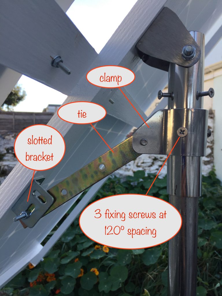
As you can see, the clamp fits around the bottom of the pole-top mount tube and is connected to the frame via a tie and slotted bracket.
The angle of the frame and solar panels can be adjusted as the year progresses by a combination of adjusting the position of the clamp on the pole and changing the position of the tie in the slotted bracket.
It really needs a much longer bracket and slot and then the required angle could be set without moving the clamp. But for the life of me I can’t find one online, so it’ll have to do as is for now 🤪
Solar panels
After mounting them on the frame, I used MC4 Y-connectors to connect the solar panels in parallel and then to connect the output to the EcoFlowRiver 600 as per the photo:
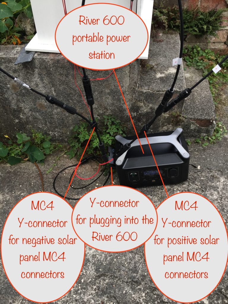
EcoFlow River 600 portable power station
This is a power station with a lithium ion based 12V 288Wh battery capable of delivering a sustained 600W, with an x-boost mode that delivers 1200W (but only one of the ac outlets can then be used).
It uses MPPT to maximise the power take-up from the solar panels and has an inbuilt inverter to give a pure sinewave 240VAC (UK / Europe model)
In the UK / Europe, if it’s being used to power AC appliances that are earthed, then the provided earthing screw needs to be connected to earth to maintain electrical safety.
Outdoors the earthing screw gets connected via an earthing (aka grounding) cable – literally a stake that you drive into the ground.
If using the River 600 inside a house (UK / Europe), then connecting the mains charging cable to it (but not switching it on) will do the earthing job equally well.
Even when not switched on, the earth coming in on the charging cable remains connected, so providing an earth route for any appliances plugged into the three pin power sockets on the River 600.
As the EcoFlow River 600 will be inside my house, a 15m PV extension cable run is needed. I’ll be using 6mm² (10 AWG) cable.
Ideally I’d use 10mm² (7 AWG) to keep losses at 10A – the maximum input current the River 600 can take – to an acceptable 5%. Unfortunately the cost of that cable is prohibitively expensive. To work things out, I used the DC Cable Sizing Tool here.
Solar charge controller
Before I can connect up the solar charge controller for the motor-driver battery, I need a way of connecting its input to the solar panel ouptut.
I’ll tap into and solder a short length of twin core cable to the positive and negative MC4 cable branches – the ones that come from the output of the Y-connectors that connect the panels in parallel. I’ve got some self-amalgamating rubber tape so I’ll use that to tightly cover the connection points and so make them weatherproof.
I’ll need a diode in the positive line feeding the charge controller so that it’s isolated from the River 600. A Schottkey 5 amp one will do the trick nicely. See the block diagram below.
Step-up buck converter
In the last post I explained how I decided to use a cradle with a counterweight because the motor didn’t have enough torque to do the lifting on its own.
It wasn’t a solution that I was really happy with, making access to the innards of the box rather cumbersome.
So after another brainwave, I decided to use a step-up converter to up the voltage supplied to the motor and so increase the torque that way. After some playing around, I found that 18V did the trick. So I’ve now removed the cradle.
Block diagram
Here’s a block diagram showing how the various blocks interconnect. Note that D2 (a 5 amp Schottky diode) prevents the solar charge controller and the EcoFlow River from interfering with each other:
Reduced the height of lift-and-twist pole
The pole height was too great – even in a gentle-ish breeze the whole lot was just too unstable. The solar panels really caught the wind and the long pole, acting like a lever, put a lot of strain on the box.
So I reduced the length of the lift-and-twist pole so that the frame, when fully vertical, just cleared the top of the box.
That made a big difference and I’m happy with the result. That’s not to say the whole assembly won’t need anchoring, just that I’ve minimised the amount needed.
I was worried that in a strong wind, the pole could bend or be torn off its mounts insde the box. I’m less worried now 🤞
Next steps
Strong-ish winds (36mph) are forecast for tomorrow – fingers crossed that everything holds up! 🤞
Waiting for the replacement motor..
The existing motor rotates just too quickly, overshooting where it should stop.
So I’ve tracked down and ordered a 12V 2.2rpm motor with a torque of 90kgf.cm (8.8Nm). It should have more than enough power to lift the solar panel frame assembly and will definitely be slow enough to stop the overshoot.
It also helps a little that the weight has been reduced by around 0.5kg due to the shorter the pole length.
Mounting the whole structure
I’ve ordered a 1.2m 35mm diameter aluminium tube with a wall thickness of 2mm and bought a stainless steel one from a local marine supplies store. It’s 28mm diameter and also has a wall thickness of 2mm.
Whatever solution I go with for locating the tracker in my garden, at least I’ve now got the poles to mount the box on. I’ve also ordered some extended u-bolts and cradles to mount the box on the poles.