(click for a larger image in a new tab / window)
In the last post I mentioned a challenge:
If the day is overcast and stays that way for a few hours, then when the sun does come out to play, it’ll be sideways on, or behind the sensor solar panel. That means no lifting and twisting can happen.
I went on to suggest I would experiment with having an additional backward-facing sensor solar panel connected in parallel with thew normal front-facing one.
Turns out that was poor thinking. What I need is one at 90° to the front-facing one. I actually might need the backward-facing one as well.
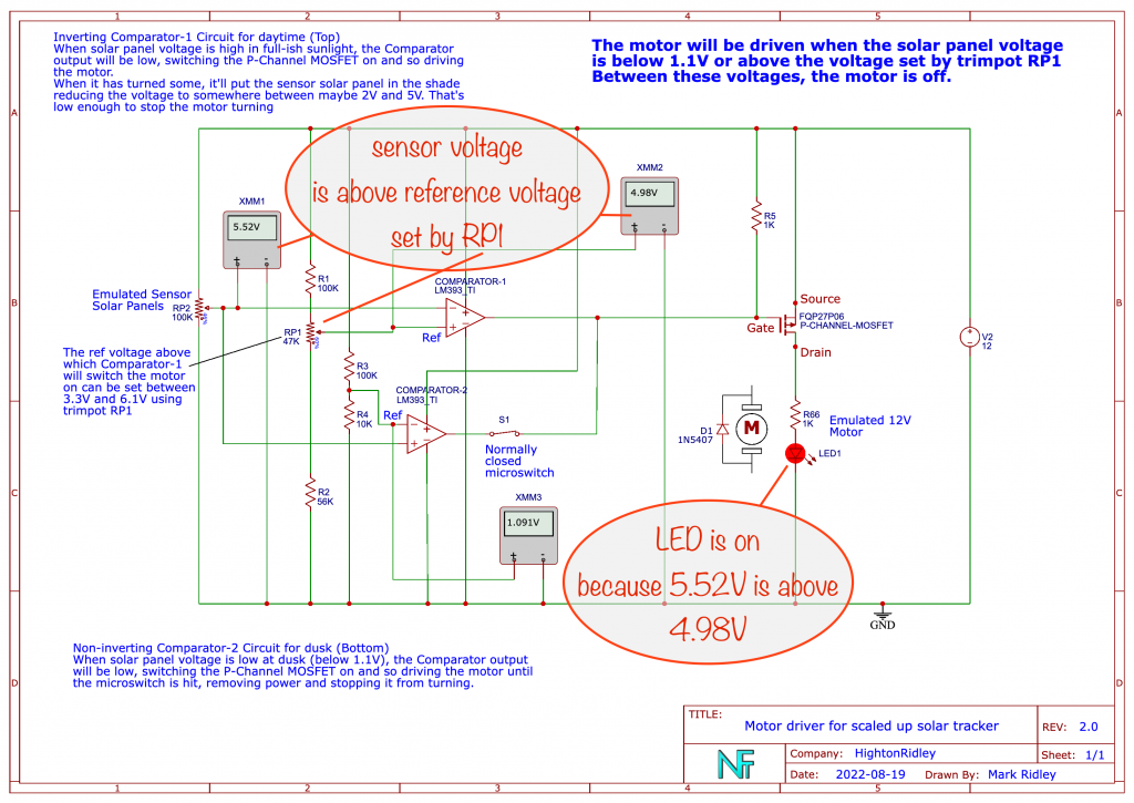
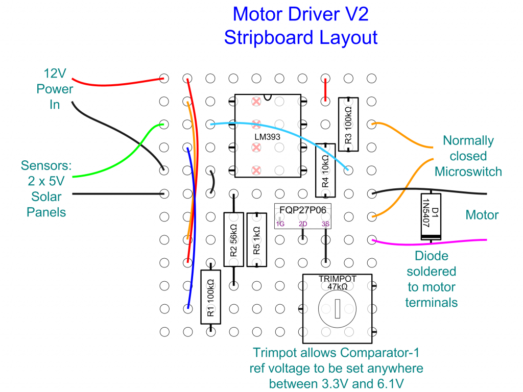
To allow for the as yet unknown effects on the overall voltage with 2 (maybe 3, later) connected in parallel as described, I’ve adjusted the motor driving circuit to allow some fine tuning.
What I’ve done is to allow the voltage above which the motor should be driven to be set by a trimpot. That way, I can experiment to find the best setting that will work for the voltage produced by the two sensor solar panels (connected in parallel) under varying conditions.

(click to open large image in new tab / window)
Mounting on the solar panel frame
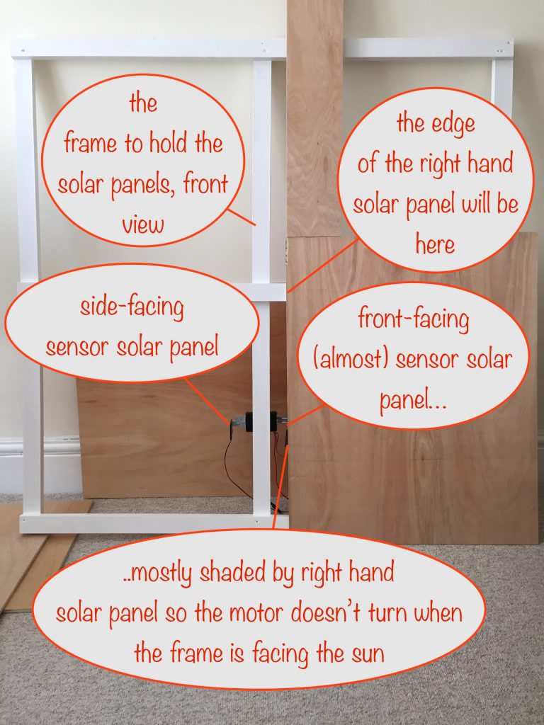
I spent a while working out how to mount the sensor solar panels onto the frame I’ve built for the main solar panels.
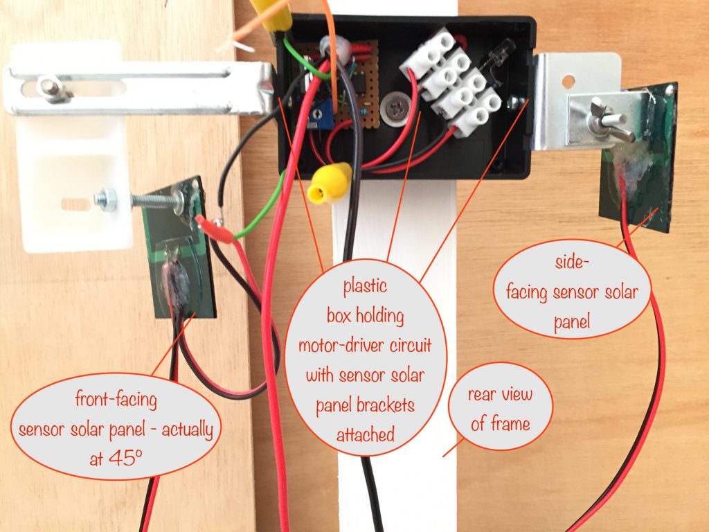
I knew I needed a box to house the motor-driver circuit and I soon realized I could attach the sensor solar panel brackets to its sides.
As you’ll see in the photos, everything’s a bit of a botch-job as I work things out.


As you can see, at this stage I’m just making sure everything can be securely mounted and that the arrangement works in practice.
I’ve still to drill holes in the box for the:
- sensor solar panel wires
- power in from the 12V leisure battery that’lll be charged by the main solar panels
- power out from the MOSFET for the motor
I might need to attach a heatsink to the MOSFET. Time will tell.
A quick reminder…
Normal operation
For this, remember that the sensor solar panels are connected in parallel.
When it’s sunny from the moment the sun rises:
- When the frame is facing the sun, the front-facing sensor solar panel is shaded, the motor isn’t powered and so no lift-and-twist happens
- As the sun moves across the sky, the right-hand main solar panel will no longer be shading the front-facing sensor solar panel. The voltage of the sensor solar panels will rise until it exceeds the voltge set by the trimpot and the motor will turn
- Lift and twist will happen and the front-facing sensor solar panel will again be put in the shade of the right hand main solar panel. The voltage of the sensor solar panels will fall until it’s below the voltage set by the trimpot and so the motor will stop turning
Operation when it’s overcast in the morning but sunny later
This is the challenge I’ve hopefully overcome:
- The sky is overcast first thing and stays that way until mid-day
- Without any morning sunshine, no lift-and-twist happens
- When the sun comes out at mid-day, it shines on the side-facing sensor solar panel
- The voltage of the sensor solar panels rises until it exceeds the voltage set by the trimpot and so the motor will turn
- As it turns, the left-facing sensor solar panel moves away from pointing directly at the sun but the front-facing sensor solar panel is moving towards the sun
- With a bit of luck and some fine tuning, the voltage of the sensor solar panels will rise enough to exceed the trimpot voltage setting and turn the motor
Well, that’s the plan!
Next steps
I’m waiting for the motor to be delivered – it should be here next week or early the week after.
When it arrives, the first thing to do is to mount it and connect it to the pulleys via the rod end bearing and rotating plate.
Then comes the big test – will it be able to lift 20kg???? It should do but, as they say, the proof of the pudding is in the eating!
Watch out for my next post when I’ll report back.