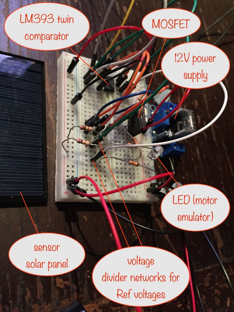
In this blog post I’m going to describe the circuit for driving the motor that’ll do the lift-and-twist, drop-and-reverse-twist.
My overall ambition is to keep any electronics to the bare minimum, so that building the circuit will be within reach of anyone with a soldering iron and a little bit of application.
Summary of where things are now
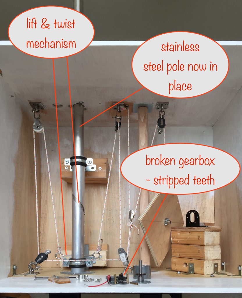
I’ve replaced the temporary wooden dowling with the stainless steel pole. Same for the lifting bearing the eyelets are attached to, so that’s progress 🙂
After the stripping of gears in my intial motor / gearbox solution 😞, I now know about the importance of calculating the required torque and getting a motor that can cope with it!
So I’ve done that and to be able to lift 20kg when the pulling point is 4.5cm from the motor shaft, I need one that can handle 4.4Nm (calculator here). As many online suppliers use units of kgf.cm, this works out at 45kgf.cm
It looks like the only motors that get close are 12V ones, which works out ok because the main solar panels will be charging a 12V battery. That means I can use the battery to drive the motor both during the day (lift-and-twist) and at dusk (drop-and-reverse-twist).
Principles for driving the motor
Initially I’m using a 6V solar panel to act as the “sensor” for deciding when to drive the motor. I’m not even considering using an LDR because of the environmental harm of the cadmium sulphide used in them.
During the day when the sensor is exposed to full-ish sunlight, the motor will turn and do a little bit of lifting and twisting – enough to put the sensor into shade behind the main solar panels.
- When the sensor is in the shade, the motor will stop turning.
- When the sun moves across the sky some more, the sensor catches the light, the motor turns and the sensor is once more put it in the shade. Repeat.
- At dusk, when the sensing solar panel is producing almost zero volts, the motor will turn until a microswitch is hit, removing power from the motor.
- When daylight arrives, the sensing solar panel will turn the motor on again (by bypassing the micro switch) and so allow the cycle to repeat.
Challenge
If the day starts overcast and stays that way for a few hours, then when the sun does come out to play 🌞 it’ll be sideways on to, or behind the sensor solar panel. That means no lifting and twisting can happen.
Sensor and Driver Circuit
Summary
I’m using a “window comparator” to monitor the voltage across the sensor. When its voltage lies outside the two defined reference voltages, a P-channel MOSFET is switched on, powering the motor.
Circuit
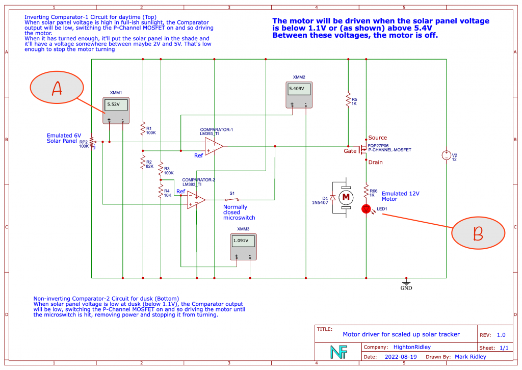
I used the free version of EDA Standard to draw and simulate the circuit before building it on a breadboard. Here’s the schematic:
(click to see full size in a new tab / window)
If you ignore the voltmeters, the solar panel, the microswitch and the motor, there’s only 8 components (the LM393 houses two comparators in one 8-pin chip) so it’s not nearly as complicated as it seems at first glance! 🤪
Circuit description
The top comparator is connected as an inverter, so that when sensor voltage is above around 5.4V (A in schematic), its output goes low, pulling the MOSFET gate down and so switching it and the motor on (B).
Its 5.4V reference voltage is set by the R1 (100kΩ) and R2 (82kΩ) voltage divider.
The bottom comparator is connected as a non-inverter, so that when sensor voltage is below around 1.1V, its output goes low, pulling the MOSFET gate down and so switching it and the motor on.
Its 1.1V reference voltage is set by the R3 (100kΩ) and R4 (10kΩ) voltage divider.
Notes
In the schematic you’ll notice I’ve substituted a potentiometer to emulate the sensor and a red LED as a substitute for the motor.
Breadboard
With everying working just fine in the simulation, next I built a breadboard version to make sure it works in reality.
Not included on the breadboard is the microswitch. In practice, as the schematic above shows, it will be at the output of comparator 2. That’s the one that comes on at dusk, causing the motor to be driven via the MOSFET whose gate is now pulled low.
When the normally closed microswitch is activated and opens, the MOSFET’s gate will not be pulled low any more (with R5 acting as a pull-up resistor), so switching it and the motor off.
When the next dawn arrives, the microswitch is bypassed because comparator 1 is the one that switches the MOSFET on and hence the motor.
I used a real 6V 0.8W solar panel (with a 330Ω resistor across its terminals to give it a little stability) so I could test that the motor would operate under the right circumstances.
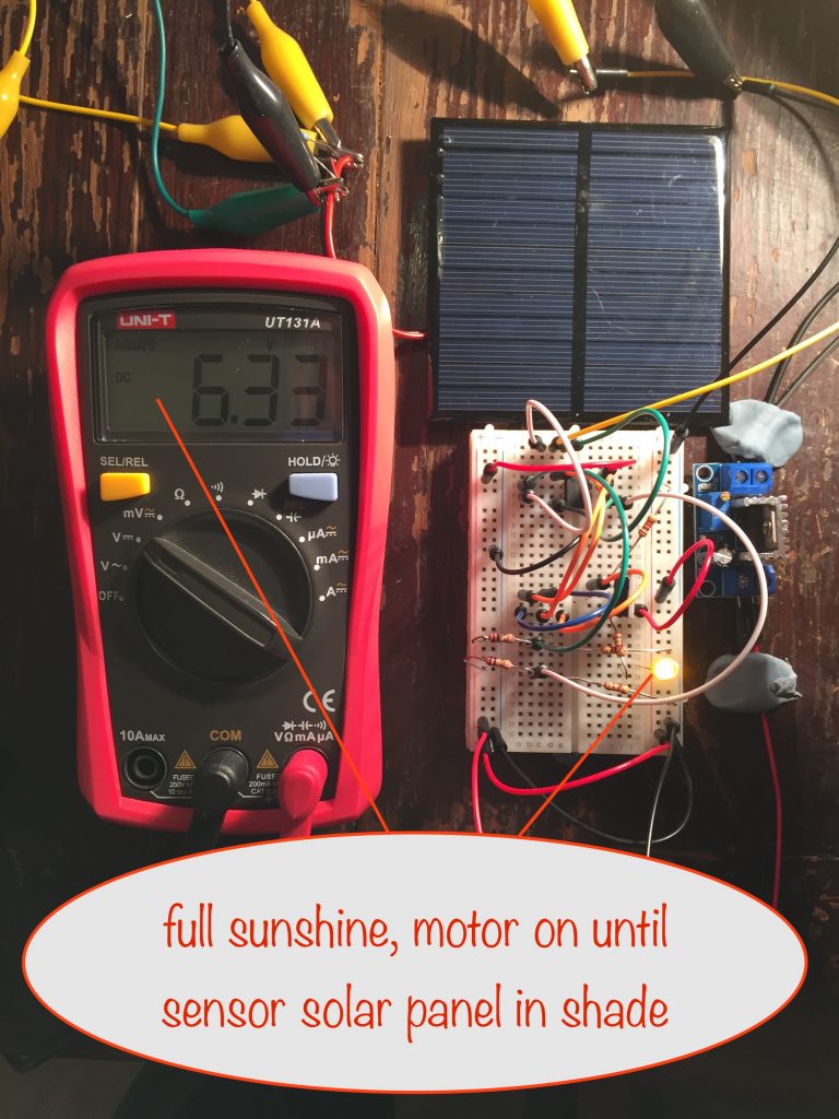
I emulated the sunshine with a bright light and you can see the results in the photos below.
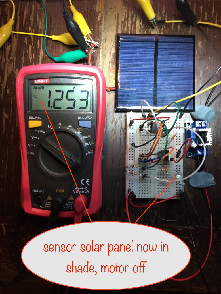
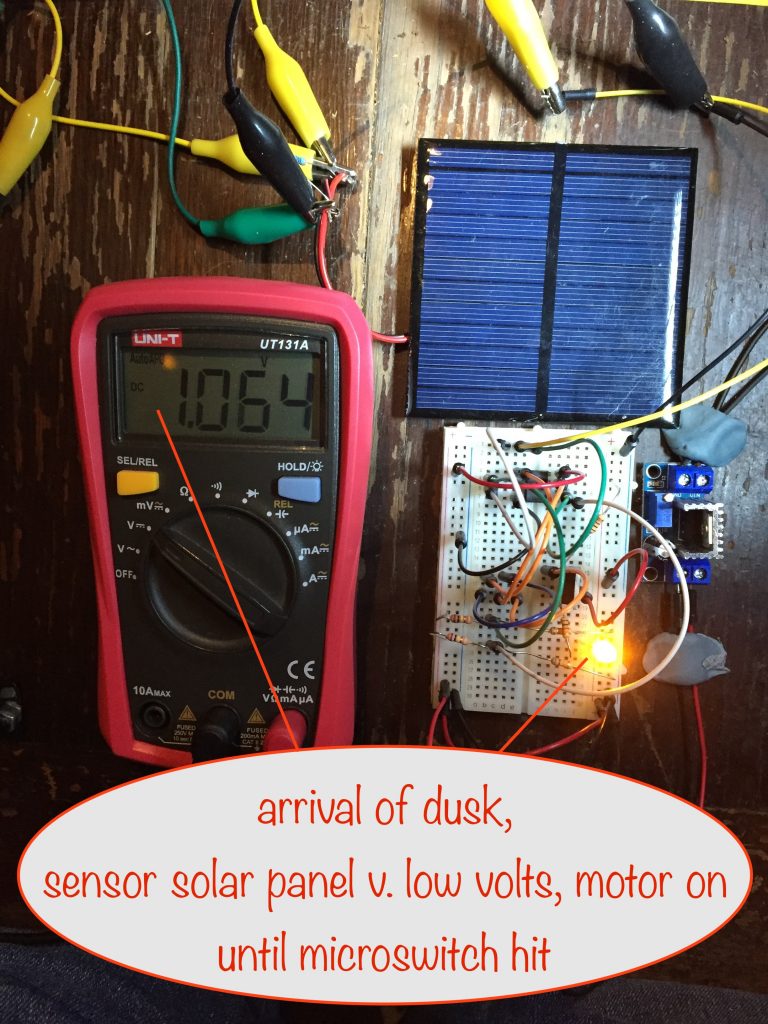
(click any to see at full size in a new tab / window)
As you can see from the photos:
- under full sunshine (above 5.4V) the motor is on
- at 1.25V (ie above 1.1V and below 5.4V) the motor is off
- at 1.06V (ie below 1.1V) the motor is on
Perfect! 🤓
Now, about that challenge
At the start of this blog post I noted that there’s a challenge to overcome:
If the day is overcast and stays that way for a few hours, then when the sun does come out to play it’ll be sideways on to, or behind the sensor solar panel. That means no lifting and twisting can happen.
I have in mind the idea of placing another solar panel on the back of and wired in parallel with the sensor one but facing in the opposite direction.
I’m not sure how that’ll go:
- in bright sunshine the overall voltage won’t reach as high because the one on the back will be at a lower voltage (less light reaching it) and so will tend to pull it down some
- when in the shade, the voltage won’t reduce as much – because the additional one will be pointing in the other direction, and won’t be shaded from the sky
- on overcast days it’ll probably increase the overall voltage, maybe causing some turning when it shouldn’t
Before I can decide if it’s the way to go, I’ve got some experimenting to do. I’ve got some low power 5V solar panels to hand so I’ll use them.
