Pole top mount design
I’ve completed the design of the mount for the pole top and have asked a local supplier to make the parts for me out of stainless steel.
click images to see larger in new tab / window
As you can see from the sketches, the design of the pole top mount allows the solar panel frame to be pointed further up or down, depending on the time of year.
Continuing the build…
Here’s the starting point for part 2 of the build
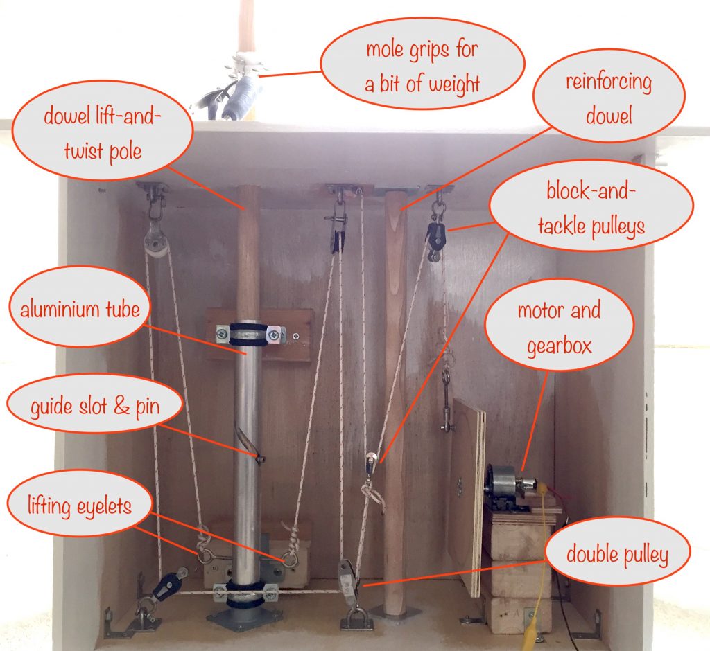
The parts I was waiting for arrived:
- the stainless steel pole
- the lifter bearing – the short length of bar with the recess for the ball bearings that the lifting eyelets attach to
- the 1:810 reduction ratio gearbox
The installation went smoothly – I used grease to hold the ball bearings in place while putting the lifter bearing in place.
I’ve now realised there’s a slight issue there as regards portability. It’s because the only thing stopping the bearings falling out (apart from the grease) is the bottom of the pole resting on them. And if the pole is to be removed for easy portability, the grease will cause some of the bearings to stick to the bottom of the pole. Hmmm….
Ok, onwards…
I coupled the 100rpm N20 motor to the gearbox and gave it a test. All went well and it was satisfying to watch the steel pole go up and down, twisting back and forth as it did so. It did take 6 mins or so for one complete cycle but that’s needed to get the required torque.
The next step was to try it out, building up to a weight equivalent to the final build and see how well everything coped. So I filled a 6 pint milk container with water and attached it to the pole as the first step.
I switched on power and, as it took the strain, the gearbox started to grind and stutter and then locked solid. Oh dear…
I removed and stripped down the gearbox and found the reason – a few teeth on some of the gears had broken off.
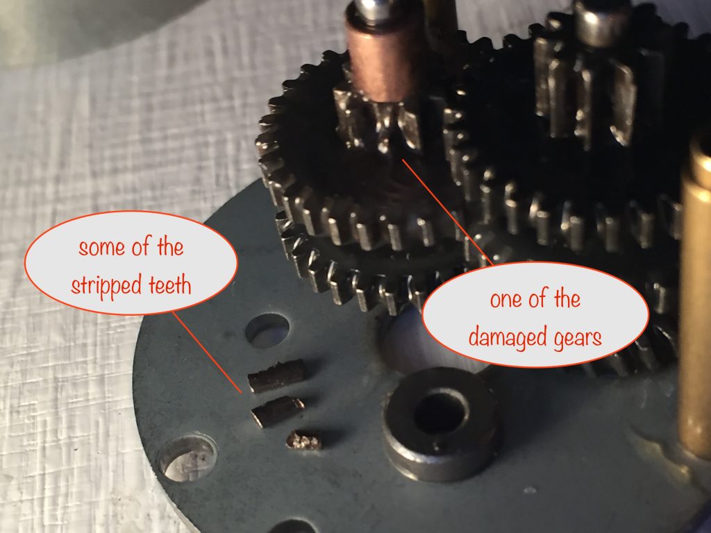
So it turns out that the speed reduction gearbox I chose simply can’t cope with the required torque – it couldn’t even cope with around a quarter of the required torque 🤪
I’ve spent a good few hours online trying to find an alternative. I’ve fired off a few emails to suppliers of those that look likely, so we’ll see.
A reminder of the mechanism’s core requirements
The motor has to be driven by a single lithium ion battery, down to 3.7v
| Requirement | Reasoning |
| The motor has to be driven by a single 18650 lithium ion battery, down to 3.7v | The readily available TP4056 charging module can, with a small mod, detect darkness and then switch the motor on until everything is reset to the sunrise position |
| Absolute minimum of 2 120W solar panels | Ideally this would be 4 solar panels, giving an additional weight of 7.2kg, but 2 would do. |
| Torque needed at a minimum is around 3.5Nm (torque calculator) | The total weight of pole, frame, top pole mount and 2 solar panels is approximately 15kg, and the lifting force is applied at a distance of 45mm from the gearbox shaft. |
If I can’t get a gearbox capable of handling the required torque, I’ll need to rethink a lot of the above. Fingers crossed! 😜