The previous final solar tracker was good for 3 x 10W solar panels (and could probably have managed a couple more).
I want to scale it up so it can cater for 400W of solar panels or better. The main hurdles to overcome:
- With increased surface area, the ability to withstand high winds
- The increased weight of 400W worth of the solar panels
- A method of mounting the solar panels on the lift-and-twist pole
- Making it portable so it can be used both at home and taken on camping holidays
- Mounting the finished build – allowing for temporary or fixed location
I think I’ve solved the first two by:
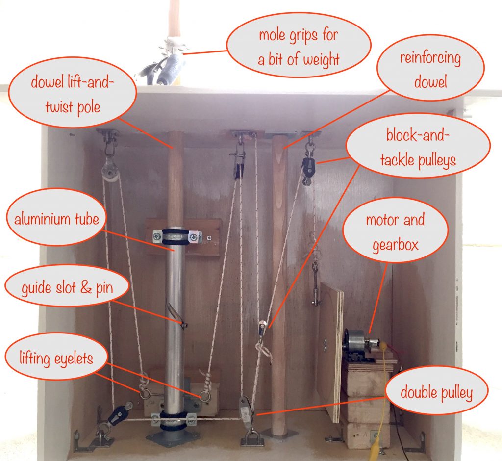
- building a box made from 9mm plywood, using reinforced metal brackets to join the sides, top and bottom together
- using a pulley system with 3mm nylon cord to do the heavy lifting, with a central reinforcer dowling to reduce the strain on the top of the box where the pulleys attach
- using a gearbox with a 1:810 reduction ratio to get much more torque than given by the 1:90 used in the earlier version.
Differences between the proof-of-concept and the actual design
While waiting for parts to be delivered, I’ve progressed with various substitutes from the actual design.
I’ve used a length of wooden dowel inside the aluminium guiding tube. The design calls for a stainless steel tube with the bottom end closed off.
The mechanism that the lifting eyelets are attached to inside the aluminium guiding tube is currently a short piece of dowel. It’ll be replaced by a 12mm high stainless steel bar, with a 2mm deep recess in the top to take some 3mm ball bearings. The closed end of the stainless steel tube will rest on the ball bearings.
I was sent the wrong gearbox – it had a reduction ratio of 1:55 instead of the 1:506 ordered. I’m fighting a battle with the suppliers to get them to replace it, so in the meantime I’ve taken the opportunity to order one from a different supplier with a 1:810 reduction ratio – as I think it’ll better be able to do the heavy lifting.
Still to resolve
I still haven’t worked out how to attach the solar panels to the top of the stainless steel lift-and-twist tube.
On the one hand, they need to be detachable for portability, and on the other, they need to be able to be fixed firmly to the tube to resist high winds.
I’m not convinced that the 2mm wall thickness of the stainless steel tube is going to be strong enough.
Once it arrives I’ll be able to test it and see if it’s ok.
Lessons learned from this proof of concept
I’m stupid, hehe!
It wasn’t until I built it that I realized the 2 times mechanical advantage gain of the block-and-tackle was entirely pointless because it meant I had to have twice the diameter on the rotating plate than I’d otherwise need.
And having twice the diameter doubles the torque needed!
For the unitiated, torque is a measure of the rotational force-at-a-distance-from-the-centre – if you increase the distance, you increase the torque needed.
Without the block-and-tackle, I only need a diameter of 4cm for the rotating plate. So I can get rid of it, simplifying things while getting the torque I need.
Read more about solar trackers
Wikipedia does a good job in covering the concepts and advantages of solar trackers.