…that starts powering attached module(s) at dusk
the Solar Lithium Ion Battery Charger is another mix ‘n match module in the Nifty Hobby Projects for LEDs and Solar series

The TP4056 board used is designed for Lithium Ion batteries and its discharge protection kicks in when the battery voltage drops to 2.5V. If you use a Lithium Polymer (LiPo) battery, that’s too low a voltage and you will damage the battery if it drops that far.
Here’s a great article about it
If you’re interested, read about Lithium Ion battery Voltage v Capacity
Keeping Safe
This module uses these safety features:
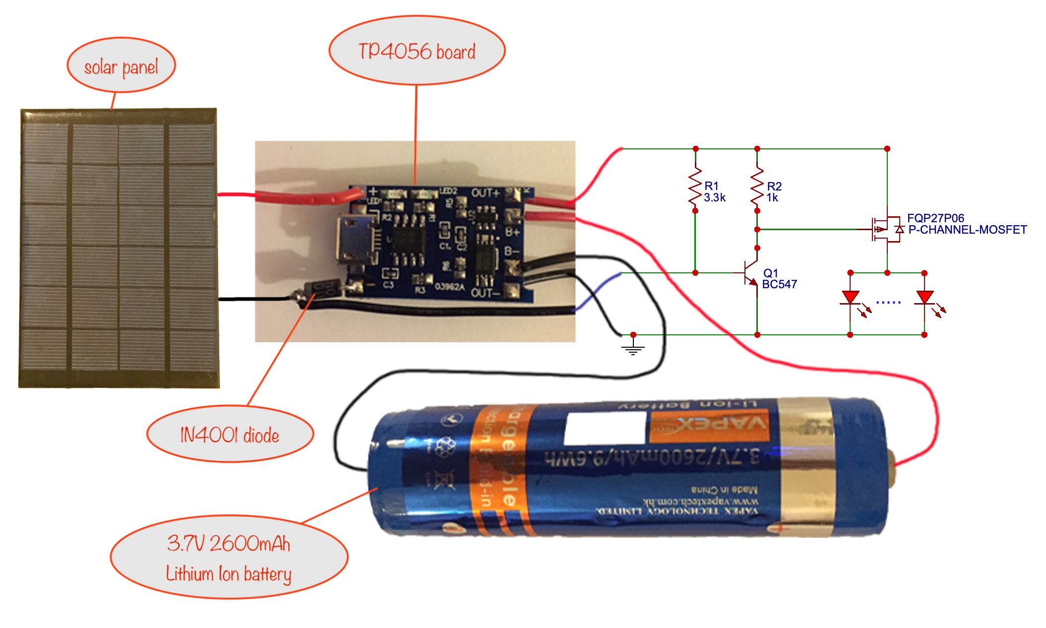
- Adding the 1N4001 diode as shown makes sure that load is only switched on when it’s dark. This means that charging and powering the load can’t happen at the same time.
Also, the diode drops the nominal 6V of the solar panel down to 5V, which is the max recommended for the TP4056 module
The reason? If we didn’t take these steps, the TP406 board wouldn’t be able to sense a full battery and could keep charging the battery even when it’s fully charged, leading to bad things like fire! - We don’t recommend using more than one Lithium Ion battery in a charging circuit because it can, under some circumstances, also lead to bad things like fire!
(click for new tab showing enlarged image)
Credits
Samual Rebosura / Edmund Brisenio: YouTube video of Solar panel Lithium Ion battery charger
The differences between the circuit here and that in the video are:
- I use a BC547 transistor to drive a P-Channel MOSFET so that a greater load can be powered. I could have used a BC377 without the MOSFET but it’s wasteful of precious battery juice. You see, the BC377 can pass 800mA continuous current through its collector/emitter but needs around 100mA through the base/emitter to drive it sufficiently to get that current. That’s four or five LEDs’ worth wasted. Using a MOSFET instead keeps nearly all of the battery juice for powering the LEDs.
(Note that the collector / emitter are swapped on the BC547 when compared to the 9013 transistor shown in the video.) - I use and recommend you use only one Lithium Ion battery, not the two shown in the video. The reason is that unless you have near identical batteries (chemistry / manufacturer / age and usage) you risk bad things, like fire!
- I use a stripboard in this project rather than having the components floating around
- output leads and a connector are recommended to allow you to mix ‘n match different modules to be powered when it gets dark. They’ll also let you include the Timer-delay Off Switch module in between the charger and the output module(s).
Tools etc. you’ll need:
- 18 Watt soldering iron, 25 Watts at a push
- “Helping Hand”
 – invaluable aid while soldering or gluing
 - Wire strippers covering 26 to 16 AWG
- Side cutters
- Small snipe-nose / needle-nose pliers
- Glue gun for weather-proofing and four or five 7mm x 100mm glue sticks
- Craft knife for cutting the flap in the plastic milk container (if that’s what you’re using for the housing)
Components List
- 1 x 18650 3.7V 2600mAh button-top Lithium Ion battery (chosen because reliable and cheap ones can be bought from componentshop.co.uk, a reputable supplier based in Wales)
- 1 x battery holder for 18650 battery with wire connectors
- 1 x 6V 1.5/2/3/4 Watt Solar Panel (see the end for a dive into the options)
- 1 1N4001 diode
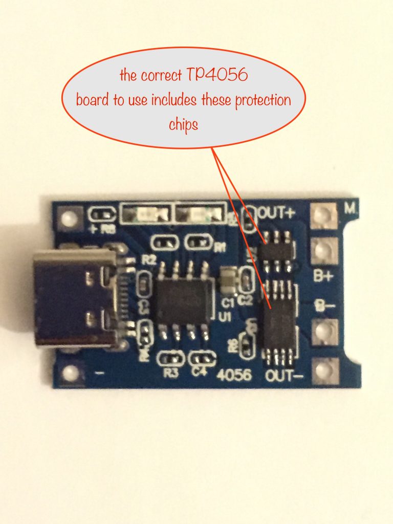
- 1 x TP4056 board with inbuilt protection (see the image below for what the correct one looks like)
- 1 x BC547 – general purpose NPN transistor
- 1 x FQP27P06 P-Channel MOSFET
- 1 x 1kΩ 1/4 watt resistor
- 1 x 3.3kΩ 1/4 watt resistor
- various lengths of red and black flexible wire for the connections
- a couple of short lengths of heat shrink sleeve
Other Bits ‘n Bobs
- Waterproof housing for the solar panel and circuit
- Connector to hook up to other modules
The Build
Preparing the TP4056 board
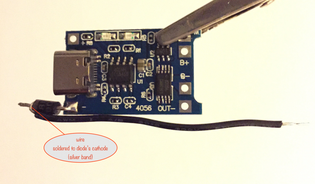
In a while, you’ll be connecting the TP4056 to the stripboard. First you have to add the 1N4001 diode and its wire.
Solder the 1N4001
The 1N4001 diode’s anode is to be soldered to the Solar Panel negative connection of the board. The anode is the end opposite the one with silver band.

(click for new tab showing enlarged image)
Solder the wires
Solder a black wire to the 1N4001 cathode (the end with the silver band). It should be long enough to allow it to be soldered to the right place on the stripboard, so give yourself plenty of room.
6cm should be enough, allowing for stripping and tinning.
Stripboard layout for driving the output
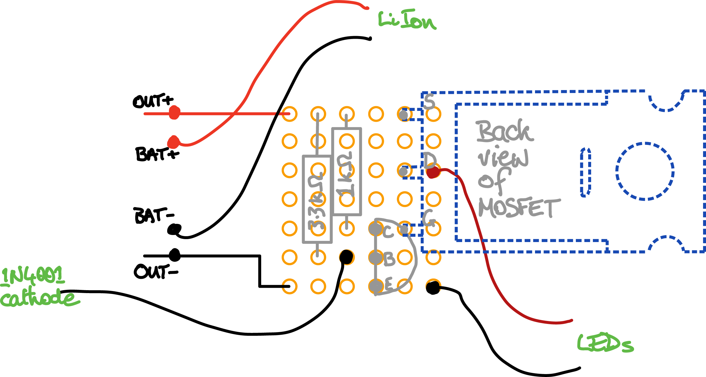
(click for new tab showing larger image)
Preparing the stripboard
Cut to size
Here’s a video showing how to cut stripboard easily
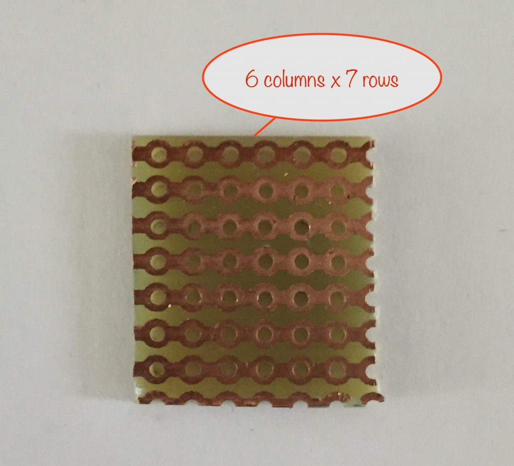
You need to cut your stripboard to 6 columns by 7 rows. Cut down the 7th column of holes and along the 8th row of holes, leaving 6 complete columns of holes and 7 complete rows of copper.
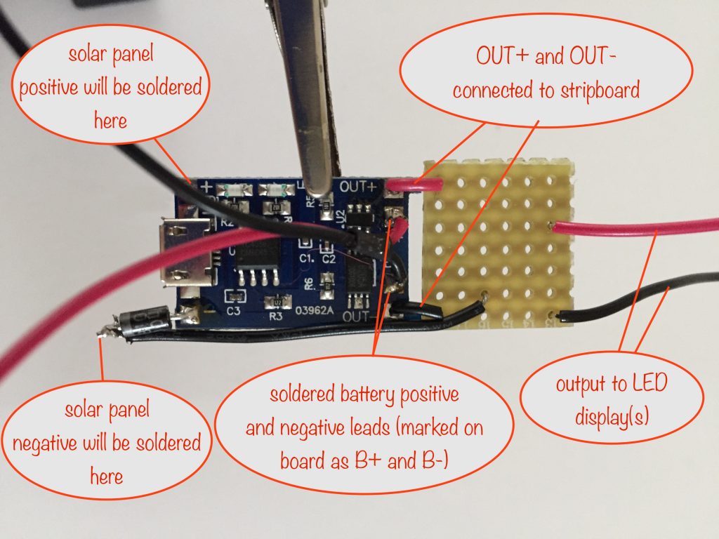
Connect the TP4056 to the Stripboard
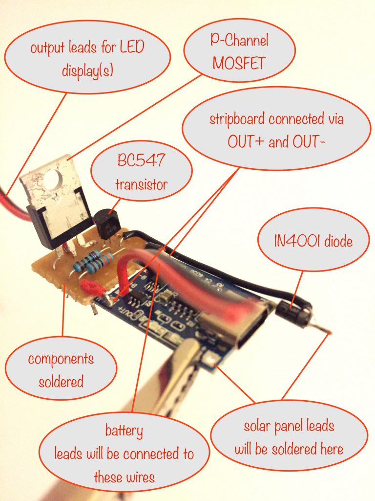
Place and solder the components
Soldering Tip 1: Don’t move a joint while the solder is still molten. Doing so can lead to a ‘dry joint’, which gives a poor / unreliable connection. Same goes for blowing on it – so don’t!
Use your snipe-nose pliers to bend the lead / legs of the components so that they reach the holes they’re meant for.
Bend the leads of the resistors and transistor so they don’t fall out when you turn the stripboard the other way up ready for soldering.
When you’ve done that, you’re ready for testing.
Testing it all works
Before starting your testing, give everything a good visual check – check all connections are correctly soldered and that the stripboard has no shorts across the copper strips.
Assuming all is good, you’re ready for testing. Good luck!
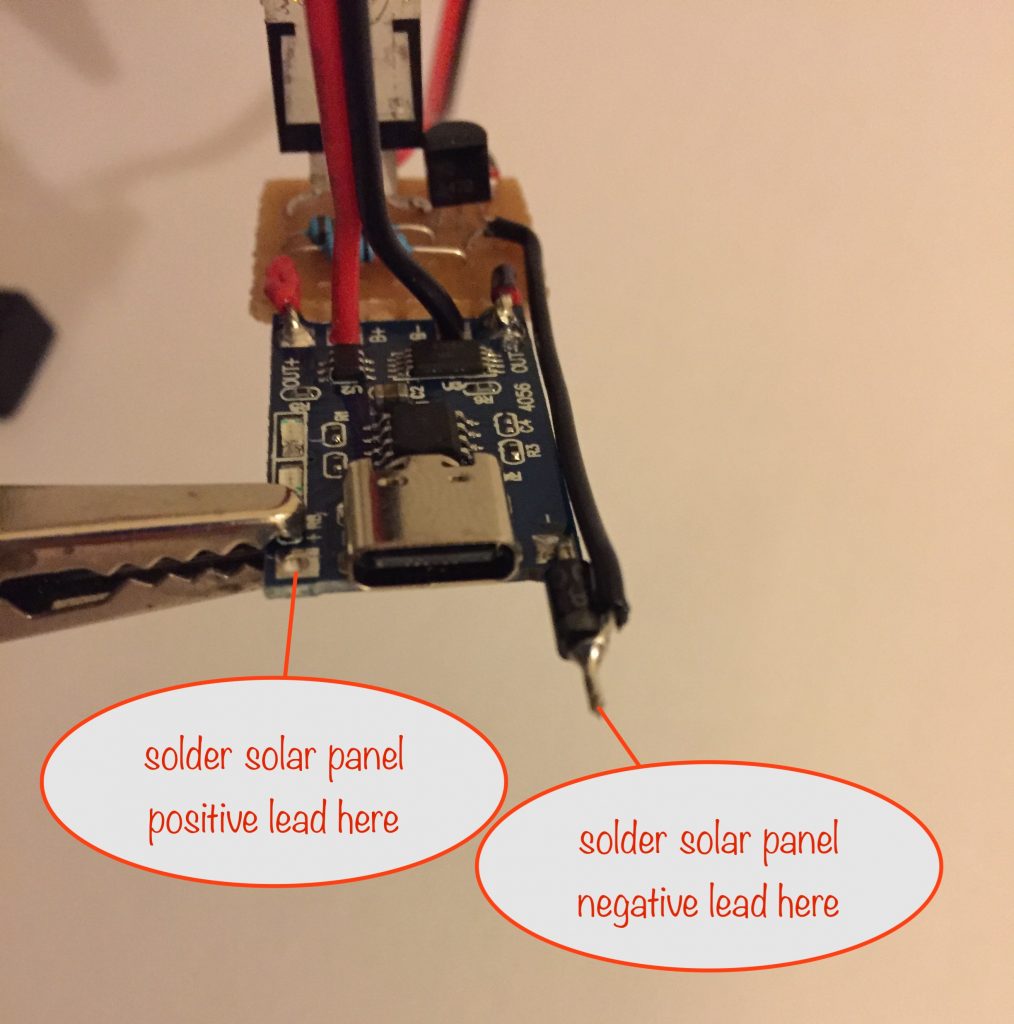
You need to start this off during daylight hours. Temporarily connect up:
- the solar panel
- a single colour-changing LED to the output leads
- the battery
Check out the photo above to see where to connect each.
Now you can point the solar panel at the sky and give it a few seconds for things to settle down.
- You should see the red charge indicator LED on the TP4056 board light up. When it’s lit it means that the battery is being charged
- If the blue charge indicator LED lights up, it means the battery is fully charged
- If they’re both lit then the battery isn’t connected correctly, so if it happens to you, double check your connections
Assuming all is good, wait for darkness to fall and when it does, the colour-changing LED should light up.
If the battery is already fully charged (blue status LED on), you can block the light reaching the solar panel and the colour-changing LED should light up. If it doesn’t, double check everything.
Mounting the solar panel and the completed circuit
Assuming all is well, you’re now ready to mount and house everything in a weatherproof container. I’ve gone with a 6 pint plastic milk container (well washed and dried). It’s the right size, it’s cheap (reuse before recycle!) and it’s perfect for the task.
Mount the solar panel
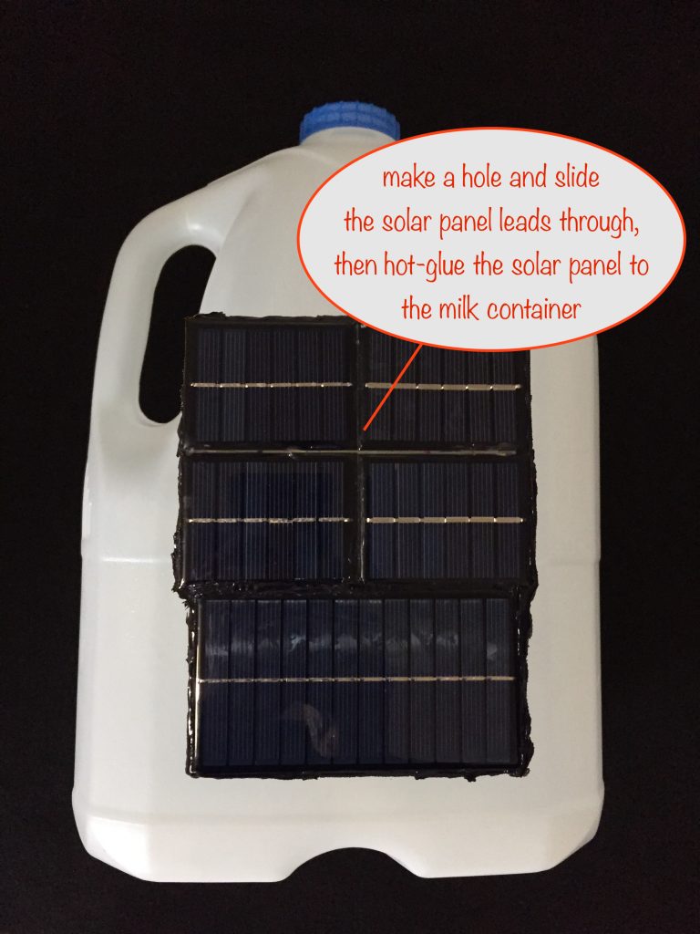
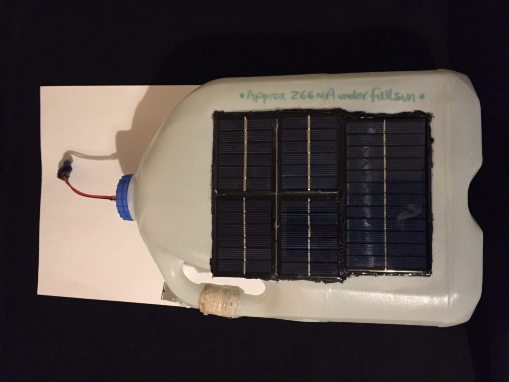
As you can see, in this prototype I’ve used not one solar panel but a combination. I’ve used two 3V 100mA solar panels connected in series to give 6V at 100mA. I’ve then done the same with another two.
I then connected the two sets in parallel, giving 6V at 200mA. I then connected a 6V 166mA solar panel in parallel with them, increasing the total current capability to 366mA.
Measured under full sun I was actually getting 266mA. Moral of the story, use one solar panel rather than combining smaller ones!
Cut the flap
Flip the milk container over and cut the flap where indicated. While you’re at it, make a small hole in the cap for the output leads to exit through.
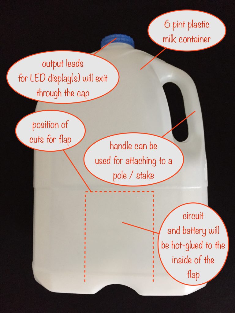
Cut the flap where indicated. After connecting up the various leads you’re going to hot-glue the circuit and the battery holder (with inserted battery) to the inside of the flap.
Connecting the leads
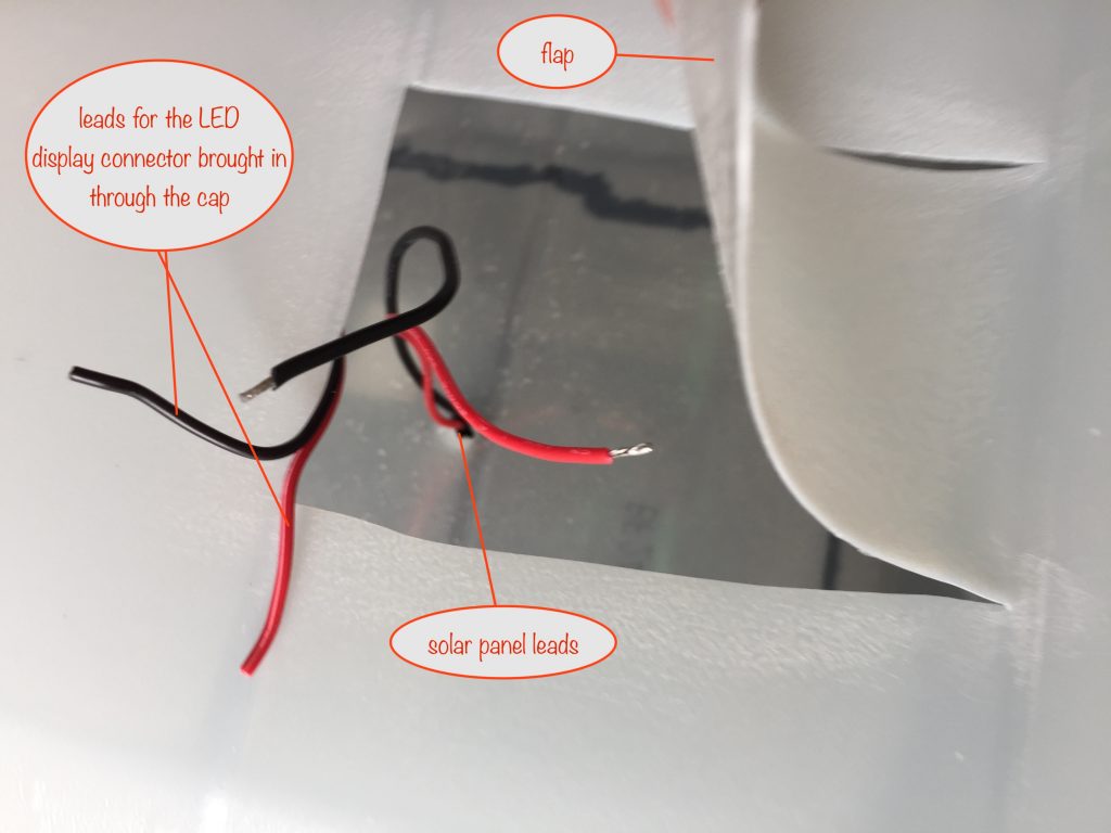
Solder the solar panel leads as shown below
You can now solder the lead you’re using for the LED display (the one that you’ve brought in through the hole in the cap) to the output leads on the stripboard. Before soldering, slip a short length of heat shrink sleeve over each.
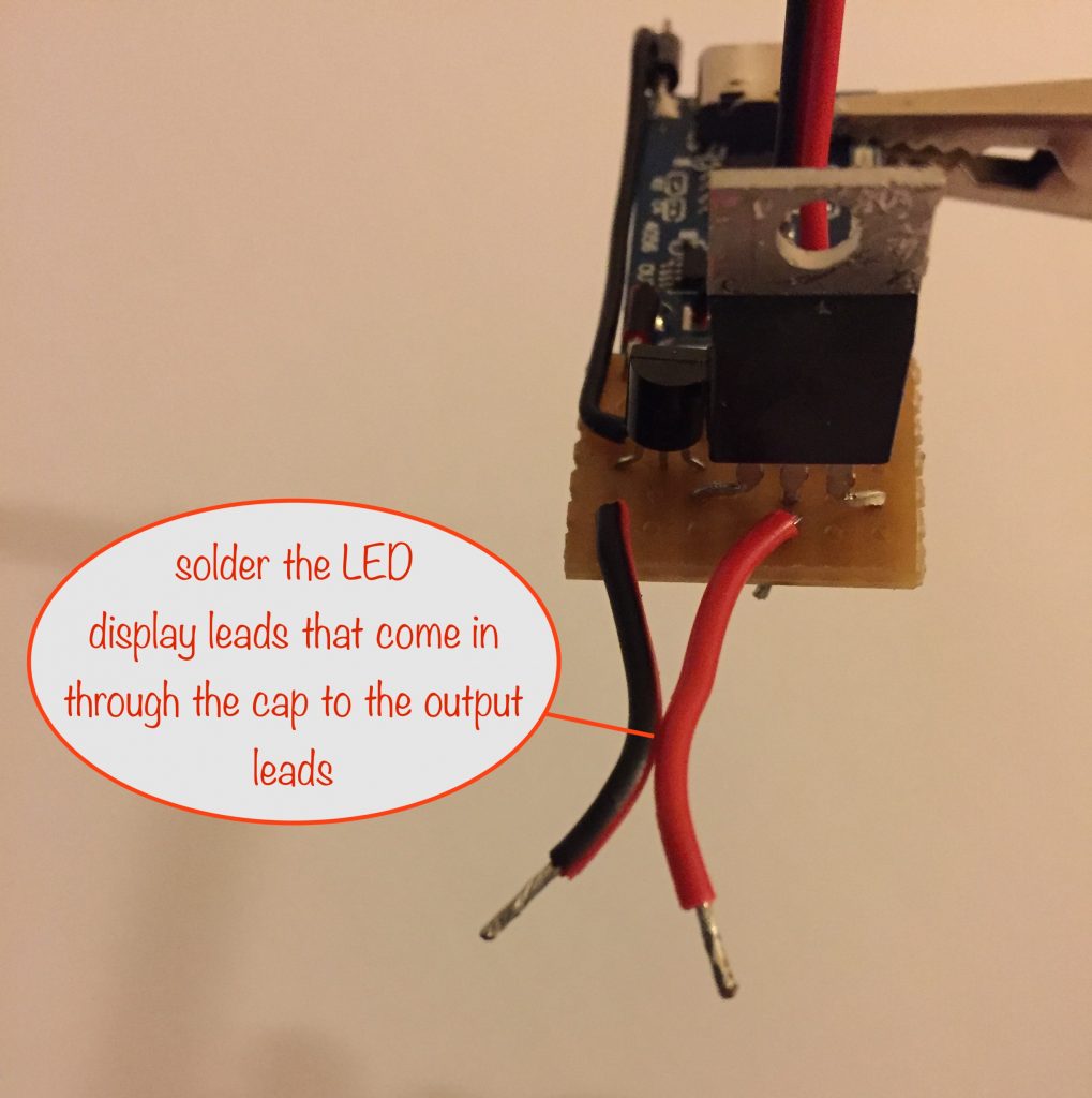
Once soldered, slip the heat shrink sleeve to cover the soldered joints and shrink into place. This will make sure they don’t short out.
Completing things
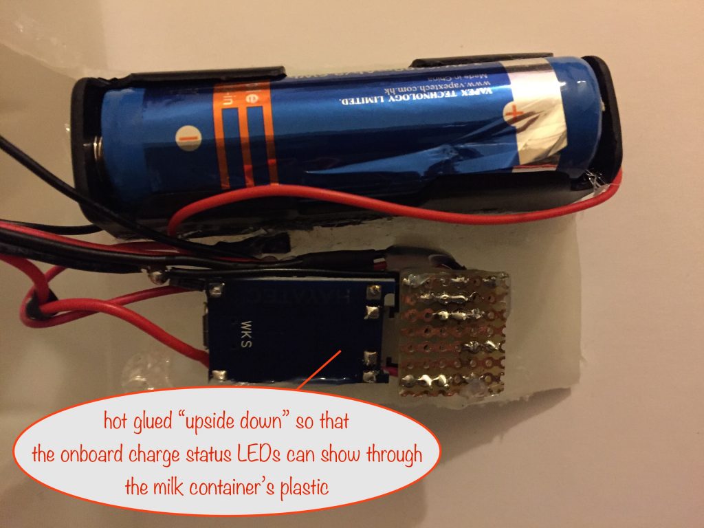
Use hot glue to attach the battery holder to the flap. Next, hot-glue the TP4056 and stripboard upside down so that the charge status indicators will be able to be seen through the plastic of the milk container.
Final check
Almost done! Before hot-gluing the the flap back into place, make sure everything still works.
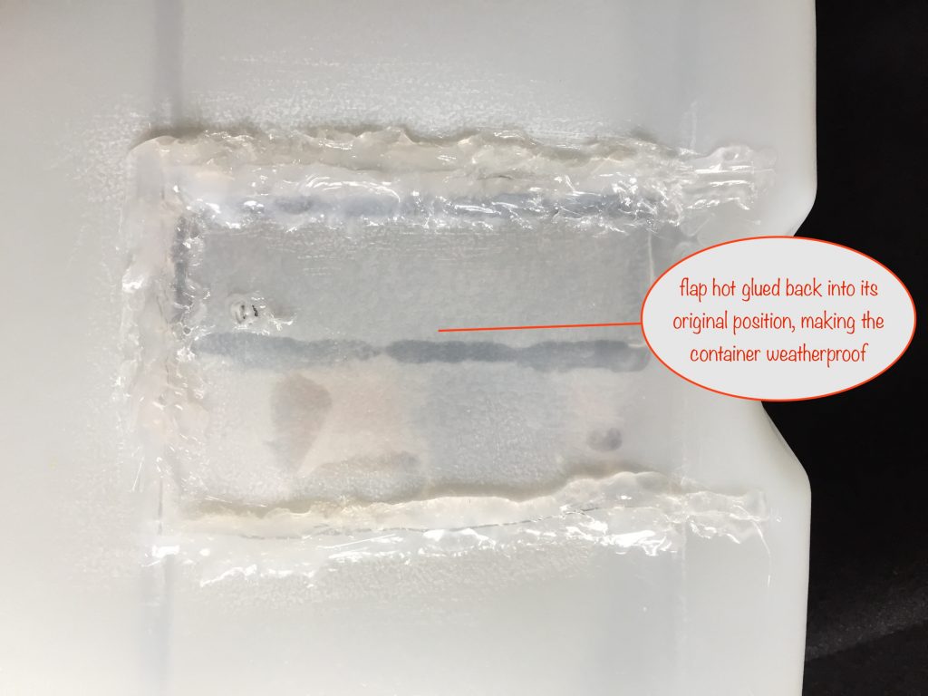
Once you’re happy, use some sandpaper to roughen along the flap edges to help with bonding. Finally, hot-glue the flap back into it’s original position, hot glue around the lead entering the cap and you’ve now got a weatherproof container.
Mounting
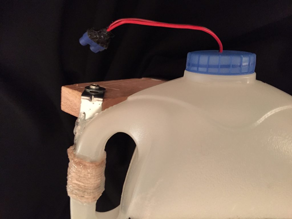
The way you mount the finished project on a stake or pole depends on what you use. For the milk container I used its handle to mount it.
I tacked a bracket to the handle with hot glue and then bound it in place by wrapping string around it and the handle. Hot glue all round the string locks it in place and shields it from the rain.
The bracket can then be screwed to a wooden stake or pole and angled to point in the best direction for sunlight throughout the day.
That about wraps it up for this module. Have fun building and using it with your choice of LED displays.
Read on to find out what goes into choosing a solar panel to suit the LED displays you want to have on show.
Options
To work out what solar panel will suit your needs we first need to work out how much battery juice is consumed by the number of colour-changing LEDs people are likley to use with it.
I tried to do a bunch of sums to work out how long various numbers of them would last, based on the amount of charge put into the battery by different wattage solar panels.
I failed miserably because the current drawn by one of those LEDs changes based on how long each of the R,G and B components are switched on. The trouble is that they don’t suddenly come on but each rises to being fully on while any others that were on fall. Too hard for this bear of simple brain to calculate!
So instead I used 33 LEDs and left them on for a couple of hours to randomize the colours being shown between them all. I then measured the current drawn to get an average per LED.
The average was 21mA (with a peak of 26mA per LED, 30 seconds after initial switch-on when they were all white).
Using a 6 Volt, 1.5Watt (= 250mA) Solar Panel
Under full sun, midsummer conditions (16 hours of daylight)
With this length of daylight and full sunlight, the battery could get 16 x 250mA = 4000mAh, limited to 2600mAh by the TP406 board sensing when the battery is “full”.
Overcast day, midsummer conditions (16 hours of daylight)
With this length of daylight and an overcast day, the battery could get 16 x 90mA =1440 mAh.
Under full sun, midwinter (December) conditions (8 hours of daylight)
With this length of daylight and full sunlight (allowing 3/5 of maximum current due to the sun being low in the sky), the battery could get 8 x 150mA = 1200mAh.
Overcast day, midwinter conditions (8 hours of daylight)
With this length of daylight and an overcast day (allowing 1/5 of maximum current due to the sun being low in the sky), the battery could get 8 x 50mA = 400mAh.
The following table summarises things for the above and also for a 2W, 3W and 4W solar panel.
| Solar Panel | Summer Sunny | Summer O/cast | Winter Sunny | Winter O/cast |
| 1.5W 250mA | fully charged | 1440mAh | 1200mAh | 400mAh |
| 2W 333mA | fully charged | fully charged | 1600mAh | 480mAh |
| 3W 500mA | fully charged | fully charged | 2400mAh | 800mAh |
| 4W 667mA | fully charged | fully charged | fully charged | 1060mAh |
How long will LEDs stay lit?
How long they’ll stay lit depends on the amount of charge available in the battery. Earlier I said the average current drawn by a single colour-changing LED was 21mA, so for 5 LEDs this would be 105mA.
A fully charged Lithium Ion battery of the type I have holds 2600mAh so a string of 5 LEDs would last 2600 / 105 = 24.7 hours.
Colour-changing LEDs don’t need current-limiting resistors because that aspect is handled by the microcontroller inside each LED.
Here’s a table showing how long the LEDs would last during Summer/Winter as per the battery charge table above. Note that times are approximate but give a good indication.
| Battery charge | 5 LEDs | 10 LEDs | 15 LEDs | 20 LEDs |
| 2600mAh (full) | 24.7 hours | 12.4 hours | 8.2 hours | 6.2 hours |
| 2400mAh | 22.9 hours | 11.5 hours | 7.6 hours | 5.7 hours |
| 1600mAh | 15.2 hours | 7.6 hours | 5.1 hours | 3.8 hours |
| 1440mAh | 13.6 hours | 6.8 hours | 4.5 hours | 3.4 hours |
| 1200mAh | 11.6 hours | 5.8 hours | 3.9 hours | 2.9 hours |
| 1060mAh | 10.4 hours | 5.2 hours | 3.5 hours | 2.6 hours |
| 800mAh | 7.6 hours | 3.8 hours | 2.5 hours | 1.9 hours |
| 480mAh | 5.6 hours | 2.8 hours | 1.9 hours | 1.4 hours |
| 400mAh | 3.8 hours | 1.9 hours | 1.3 hours | 1 hour |
From the two tables you can draw these conclusions
- during Summer, using a 6V 2W solar panel should always give you a full battery and lets you have 20 LEDs for around 6 hours or 15 LEDs for around 8 hours
- during Winter, you’d need to use a 6V 3W solar panel to make sure you get enough power for 15 LEDs for 7.6 hours – as long as you get sunny days. On overcast days, even a 4W solar panel would only get you around 5 hours when using 15 LEDs
- Alternatively, during Winter you could stick to just 10 LEDs with a 4W solar panel and still get around 5 hours after an overcast day or 12 hours after a sunny day.
Improving things
You can improve things by using the Timer-delay Off Switch module, set to switch off after 4 hours in Winter and 4 or 8 hours in Summer. Which you choose will depend on how many LEDs and the wattage of the solar panel you’re using.
After a sunny day this will preserve some charge in the battery for the following day.
Another thing you could do over Winter is to have two solar charging modules with only one connected up to a display module, allowing the other one to keep charging its battery. You could then swap them over every couple of days.
If you do choose this option, you’ll need to think about how to protect the connectors from the weather.
Possible enhancements
There’s one enhancement I’ll leave up to you to think about – the addition of some sort of switch to disconnect the MOSFET’s gate for when you want to switch off the ouptut LED display. This could be handy in Winter, switching off for a day or two to let the battery fully charge.
Hint: a reed switch and magnet could come in handy here.
Sun follower
I haven’t built this yet but it’s on the cards…
I’ve come up with a neat solution that I’ve not seen used anywhere else after a lot of searching on the internet. Thanks to Lewin Day’s YouTube video for some inspiration.
Here’s a blog post about the proof of concept for it
What do you think?
Other projects…
Other projects in the Nifty Hobby Projects for LEDs and Solar series (so far, more to come very soon):
- Flasher Memory Aid
- Dark-activated Switch
- 5 LED String
- Fibre Optic display
- Mini Sparkles Colour-changing LED Fibre Optic String
- Solar NiMH Battery Charger for 2 AAA batteries
- Solar NiMH Battery Charger for 2 AA batteries
- Solar NiMH Battery Charger for 6 AA batteries
- Timer-delay Off Switch
- 4-LED Porch Light
- 10-LED Bedside lamp
- Mini Camping / Bedtime Reading Lamp
- Main page with links to where to buy stuff