by Mark Ridley, our resident electronics hobbyist
After a few months, the acrylic tubes shattered in high winds – they couldn’t take the repeated battering. I’ve now replaced them with aluminium tubes and it’s working well.

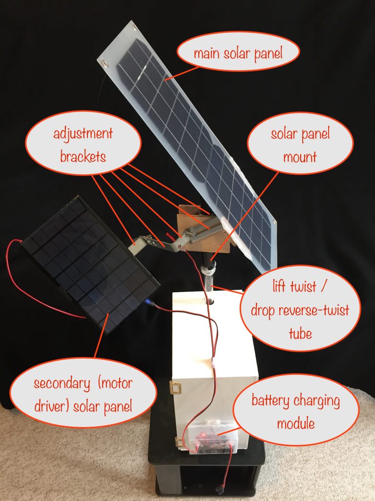
If you saw my previous post, you’ll notice that I’ve reduced the size of the solar panel mount. The end result is that the mount, including solar panels, now weighs just under 800 grams (22 oz) – down from around 1kg.
Watch it in action:
Key features
- single axis sun tracking
- two solar panels:
- a main one for battery charging and dark detection
- a secondary one for driving the sun tracker motor
- the main solar panel feeds a TP4056 module to charge a single Lithium Ion 3.7v battery (see how to build one). When it gets dark it’s switched automatically to power, for example, a string of garden LEDs
- at the same time, the battery briefly drives the motor to reset the solar panels to their morning position
- unique lift and twist / drop and reverse-twist mechanism:
- solar tracking by lift and twist
- solar panels reset to their morning position by drop and reverse-twist
- a plate attached to the sun tracker motor shaft provides the lifting force via a length of nylon braid and offset pin
How it works
Lift and Twist, Drop and Reverse-Twist mechanism
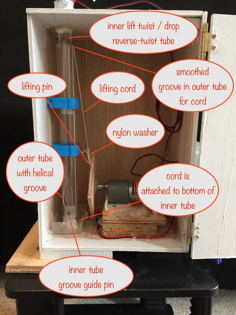
- two acrylic tubes are used, one inside the other, with the solar panel mount sitting atop the inner one
- the outer acrylic tube has a 180° helical slot cut in it, 8cm from top to bottom
- the inner tube has a pin that fits into the helical slot so that, as it’s lifted by 8cm, it’s forced by the slot to rotate by 180°
- when the inner tube is allowed to drop, the pin once more is guided by the helical slot, twisting the tube back 180° to its starting position.

- a length of braided nylon cord (braided to prevent stretching) is attached to the bottom of the inner tube. It goes up between it and the outer tube and continues down the outside
- as it goes up and over the top of the outer tube, it goes via a smoothed slot, down to a nylon washer that’s hooked over a lifting pin in a plate attached to the driver motor’s shaft
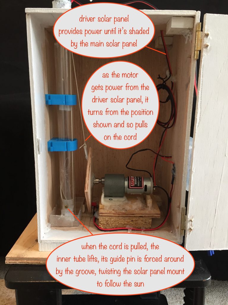
- the motor rotates in one direction only and as it rotates through the first 180° it pulls on the nylon cord, lifting the inner acrylic tube and causing it to twist by the full 180° by the time it’s reached the top of its travel
- the pin the nylon washer is hooked over is offset from the center of the plate by 4cm so that its attached cord gets pulled a total of 8cm for the first half a revolution
- as the motor rotates in the same direction through the second half revolution, it relaxes the pull on the nylon cord, allowing the inner tube to drop the 8cm and so reverse-twist back by 180°
Powering the sun-tracker motor during the day
During the day, the secondary solar panel drives the motor when unshaded by the main solar panel (and the sun is shining).

- at dawn the secondary solar panel (the motor driver) is shaded by the main one until the sun moves a little across the sky
- when the driver solar panel is out of the shade, power is delivered to the motor which causes the solar panel mount to rise and twist, chasing the sun
- this puts the driver solar panel back into the shade of the main one and, without power, the driver motor stops.
The end result is that the main solar panel is once again pointing at the sun and this continues throughout the day as long as there is enough sunshine.
Returning the solar panels to their morning position when darkness falls
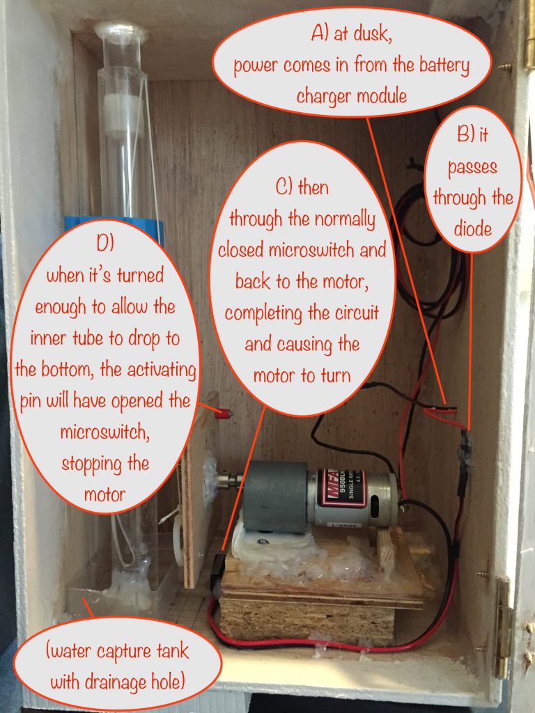
This is the really cool part! At dusk the main solar panel stops providing power to the battery charger module. This causes its output circuit to switch on power, for example, to an attached garden LED string.
That’s its normal function – and we make use of it to reset the solar panels as described below.

- When the output circuit of the battery charging module is switched on, it cunningly also delivers power to the motor
- if they weren’t already at the top of their travel, the solar panels will first rise and twist before falling and twisting, heading back towards their morning position
- the motor keeps rotating until the activating pin on the plate hits the micro switch, stopping output power from the battery reaching the motor
- the activating pin is cunningly placed so that when it hits the micro switch, the inner tube is at the bottom of its travel, thus leaving the solar panels reset to their morning starting point
I’ve also included a water capture ‘tank’ with a drainage hole. This makes sure that any rainwater running down the inner tube from the outside gets returned to the outside.
I used the tip of a plastic nozzle I’d kept in my box of bits (from an emptied tube of silicone sealant) to line and poke out the bottom of the drainage hole. That way the water is guided away from the bottom of the box.
Hopefully it’s wide enough to do as needed without being so wide that it makes a cozy home for any little beasties!
NB On an overcast day, it doesn’t really matter in which direction the solar panel points because scattered light comes in pretty much equally from all directions. If they haven’t moved from their morning position nothing happens when darkness falls because the micro switch is still activated (ie open). If they have, the motor will be powered by the battery to reset them back to the morning position as described above.
Lessons Learned and Next Steps
- Despite the passing of the years, being older and wiser does not a carpenter make!
- Hot glue is truly wonderful – with a hairdrier on the hot setting, it’s easy to correct mistakes
- Don’t leave positioning the microswitch to last as I did, it’s a right old fiddly pain that would have been so easy if I’d done it earlier!
- It’s approaching the shortest day of the year as I write this and already my garden gets no sunlight during the day because the sun is too low in the sky and the buildings around me block it out. It was fine up to mid-october but not any more.
In a future enhancement I’ll use a long extension tube between the lifting tube and the solar panel mount so it can reach up to to where the sun does shine! I’ve got a washing line pole so should be able to to brace it with that. We’ll see. - The motor I’ve used needs a larger powered solar panel to drive it than I’m happy with. It’s because of its current draw – I’d like to get it down from around 120mA to maybe half that.
- It should be really easy to add additional main solar panels and battery charger modules. Each additional main solar panel won’t add much to the weight that needs to be lifted.
- It should be a piece of cake to swap out the Lithium Ion battery charger module and instead use one to allow a 12v leisure battery to be charged. The main solar panel would also need to be swapped but that’s no hardship.
- The only remaining possible issue is how it will hold up to high winds but only time will tell.
Well, it’s been a fun project getting to this stage, very apposite given that COP26 in Glasgow has just finished.
I hope I’ve inspired you to start using renewable energy for your own projects. Please let me know in the comments 😎
One last idea – instead of just charging a battery with a solar panel, you could also fix some form of mirrored surfaces to the mount to direct sunlight into areas of your garden that don’t get much sunshine.
One thought on “Solar Tracker Prototype – now complete”