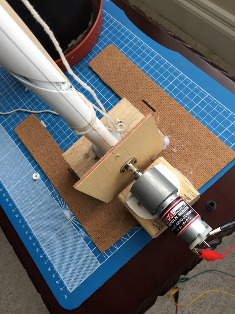
The previous motor was drawing too much current to be practical for the hobby solar panel I intend to use as the driver for it on the project.

After a little hunting on the web, I found a likely candidate from the same manufacturer. A quick email confirmed that the motor was likely to do the job so I placed an order and waited a couple of days.
I’d also ordered a hub for connecting it to the rotating plate and it arrived on the same day. So after a quick swap and using some fishing line instead of thread I was ready for a test.
Perfect 😎
The plastic tubing I’m currently using in my prototype is too bendy, so I’ve swung the pendulum the other way and ordered some aluminium tubing.
I know it’s overkill for the combined weight of the solar panel, the driver solar panel, the circuitry and the enclosure but it’ll do for now.
A good friend is putting the helical slot into the outer aluminium tube because I don’t have the tools for it. He’s also promised a fancy 3D printed roller for the top of the tube to lift the fishing line away from the tube’s edge and so prevent it fraying.
I’ve ordered some clear acrylic and some rigid pvc tube today so I can see how they work out. Hopefully they’re rigid enough so they don’t flex but soft enough to make it easy for hobbyists to work with.
How it works
Principle
In the video you’ll see I’ve tied an old paintbrush to the outer tube to stop it bending.
The fishing line goes up from the rotating plate, over the top of the outer tube and is fixed to a slot in the bottom of the inner tube.
As the plate rotates (it always rotates in the same direction), it pulls on the fishing line, which then lifts the inner tube.
As it lifts, it’s forced to rotate by its pin being constrained in the helical slot cut in the outer tube. The helical slot forces it to rotate clockwise by approx 180° for the first half a revolution of the motor, counter clockwise for the second half.
Here’s the video:
In practice
In practice, the milk container will be replaced by:
- a mounted solar panel
- the battery and charging circuit
- a smaller driver solar panel for the motor
Start of day
- The main solar panel is facing in the direction of sunrise
- The driver solar panel will be shaded by the main one when the sun rises
- When the sun moves across the sky some, the driver solar panel is less and less shaded until it gets enough light to power the motor
- The motor turns the plate, lifting the inner tube and rotating the main solar panel until the driver solar panel gets more and more shaded by the main one
- When it’s shaded enough, the motor switches off and the main solar panel is now pointing directly in the sun’s direction.
Not enough sun?
If there’s not enough sun to power the driver motor, the main panel remains pointing wherever it happens to be.
That’s ok because on a cloudy day, it doesn’t really matter as the main solar panel will get roughly the same amount of light whichever direction it points in.
End of day
- When dusk falls, there’s no longer any power from the main solar panel and so the circuit isn’t charging the battery any more
- When that happens, the Solar Lithium Ion Battery Charger module circuit as designed will start powering its connected load (an LED String module for example) and at the same time will supply power to the driver motor
- The motor will start turning (no matter in which direction the main solar panel is facing) until the helical slot returns the inner tube to the bottom of its travel
- As the motor turns, it’ll raise it first, if it wasn’t already at the top
- As it reaches the bottom:
- the main solar panel is now pointing back in the direction where the sun will rise
- the magnet at the bottom of the inner tube has now reached and lines up with the normally closed reed switch at the bottom of the outer tube
- the reed switch opens, switching off the motor
- NB a diode is used in series between the battery output power and the motor to prevent current back-flow through the driver solar panel
I’ll write another blog post when I’ve got the prototype to the next stage. Come back soon!