Blog

Scaled-up Solar Tracker – proof of concept part 3

see part 2 :: see part 4

In this blog post I’m going to describe the circuit for driving the motor that’ll do the lift-and-twist, drop-and-reverse-twist.

My overall ambition is to keep any electronics to the bare minimum, so that building the circuit will be within reach of anyone with a soldering iron and a little bit of application.

photo of the
one step forward and two steps back – after the gear-stripping incident

Summary of where things are now

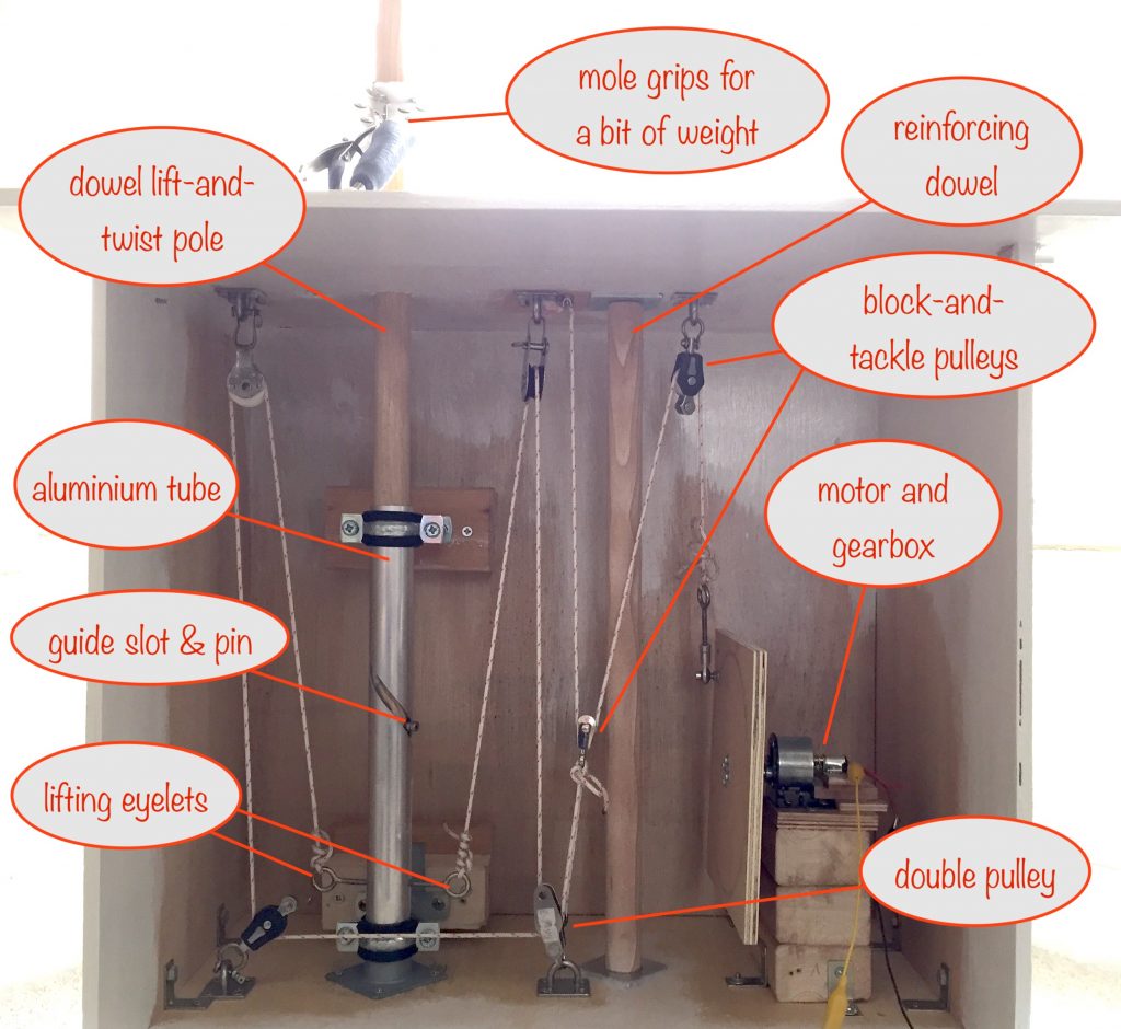
I’ve replaced the temporary wooden dowling with the stainless steel pole. Same for the lifting bearing the eyelets are attached to, so that’s progress 🙂

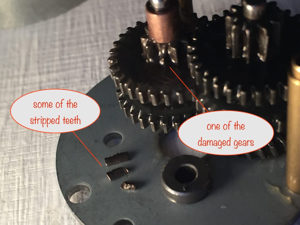
After the stripping of gears in my intial motor / gearbox solution 😞, I now know about the importance of calculating the required torque and getting a motor that can cope with it!

So I’ve done that and to be able to lift 20kg when the pulling point is 4.5cm from the motor shaft, I need one that can handle 4.4Nm (calculator here). As many online suppliers use units of kgf.cm, this works out at 45kgf.cm

It looks like the only motors that get close are 12V ones, which works out ok because the main solar panels will be charging a 12V battery. That means I can use the battery to drive the motor both during the day (lift-and-twist) and at dusk (drop-and-reverse-twist).

Principles for driving the motor

Initially I’m using a 6V solar panel to act as the “sensor” for deciding when to drive the motor. I’m not even considering using an LDR because of the environmental harm of the cadmium sulphide used in them.

During the day when the sensor is exposed to full-ish sunlight, the motor will turn and do a little bit of lifting and twisting – enough to put the sensor into shade behind the main solar panels.

  1. When the sensor is in the shade, the motor will stop turning.
  2. When the sun moves across the sky some more, the sensor catches the light, the motor turns and the sensor is once more put it in the shade. Repeat.
  3. At dusk, when the sensing solar panel is producing almost zero volts, the motor will turn until a microswitch is hit, removing power from the motor.
  4. When daylight arrives, the sensing solar panel will turn the motor on again (by bypassing the micro switch) and so allow the cycle to repeat.

Challenge

If the day starts overcast and stays that way for a few hours, then when the sun does come out to play 🌞 it’ll be sideways on to, or behind the sensor solar panel. That means no lifting and twisting can happen.

More on this later.

Sensor and Driver Circuit

Summary

I’m using a “window comparator” to monitor the voltage across the sensor. When its voltage lies outside the two defined reference voltages, a P-channel MOSFET is switched on, powering the motor.

Circuit

I used the free version of EDA Standard to draw and simulate the circuit before building it on a breadboard. Here’s the schematic:

a schematic of the Sensor and Driver Circuit with two points of interest marked A and B
schematic of Sensor and Driver Circuit
(click to see full size in a new tab / window)

If you ignore the voltmeters, the solar panel, the microswitch and the motor, there’s only 8 components (the LM393 houses two comparators in one 8-pin chip) so it’s not nearly as complicated as it seems at first glance! 🤪

Circuit description

The top comparator is connected as an inverter, so that when sensor voltage is above around 5.4V (A in schematic), its output goes low, pulling the MOSFET gate down and so switching it and the motor on (B).

Its 5.4V reference voltage is set by the R1 (100kΩ) and R2 (82kΩ) voltage divider.

The bottom comparator is connected as a non-inverter, so that when sensor voltage is below around 1.1V, its output goes low, pulling the MOSFET gate down and so switching it and the motor on.

Its 1.1V reference voltage is set by the R3 (100kΩ) and R4 (10kΩ) voltage divider.

Notes

In the schematic you’ll notice I’ve substituted a potentiometer to emulate the sensor and a red LED as a substitute for the motor.
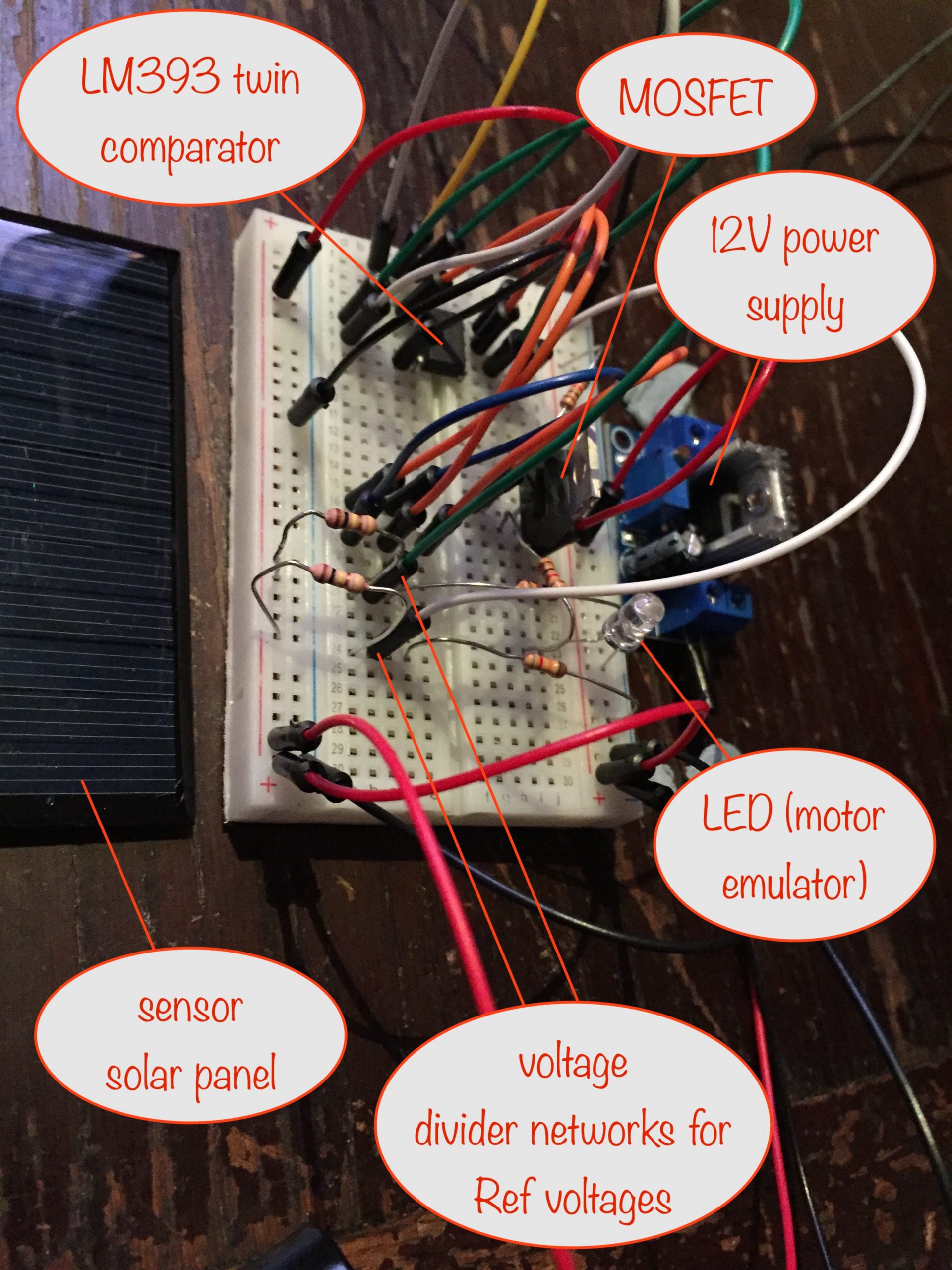
Breadboard

With everying working just fine in the simulation, next I built a breadboard version to make sure it works in reality.

a photo of the breadboard with major components labelled
the breadboard and major components
(click to see full size in a new tab / window)

Not included on the breadboard is the microswitch. In practice, as the schematic above shows, it will be at the output of comparator 2. That’s the one that comes on at dusk, causing the motor to be driven via the MOSFET whose gate is now pulled low.

When the normally closed microswitch is activated and opens, the MOSFET’s gate will not be pulled low any more (with R5 acting as a pull-up resistor), so switching it and the motor off.

When the next dawn arrives, the microswitch is bypassed because comparator 1 is the one that switches the MOSFET on and hence the motor.

I used a real 6V 0.8W solar panel (with a 330Ω resistor across its terminals to give it a little stability) so I could test that the motor would operate under the right circumstances.

I emulated the sunshine with a bright light and you can see the results in the photos below.
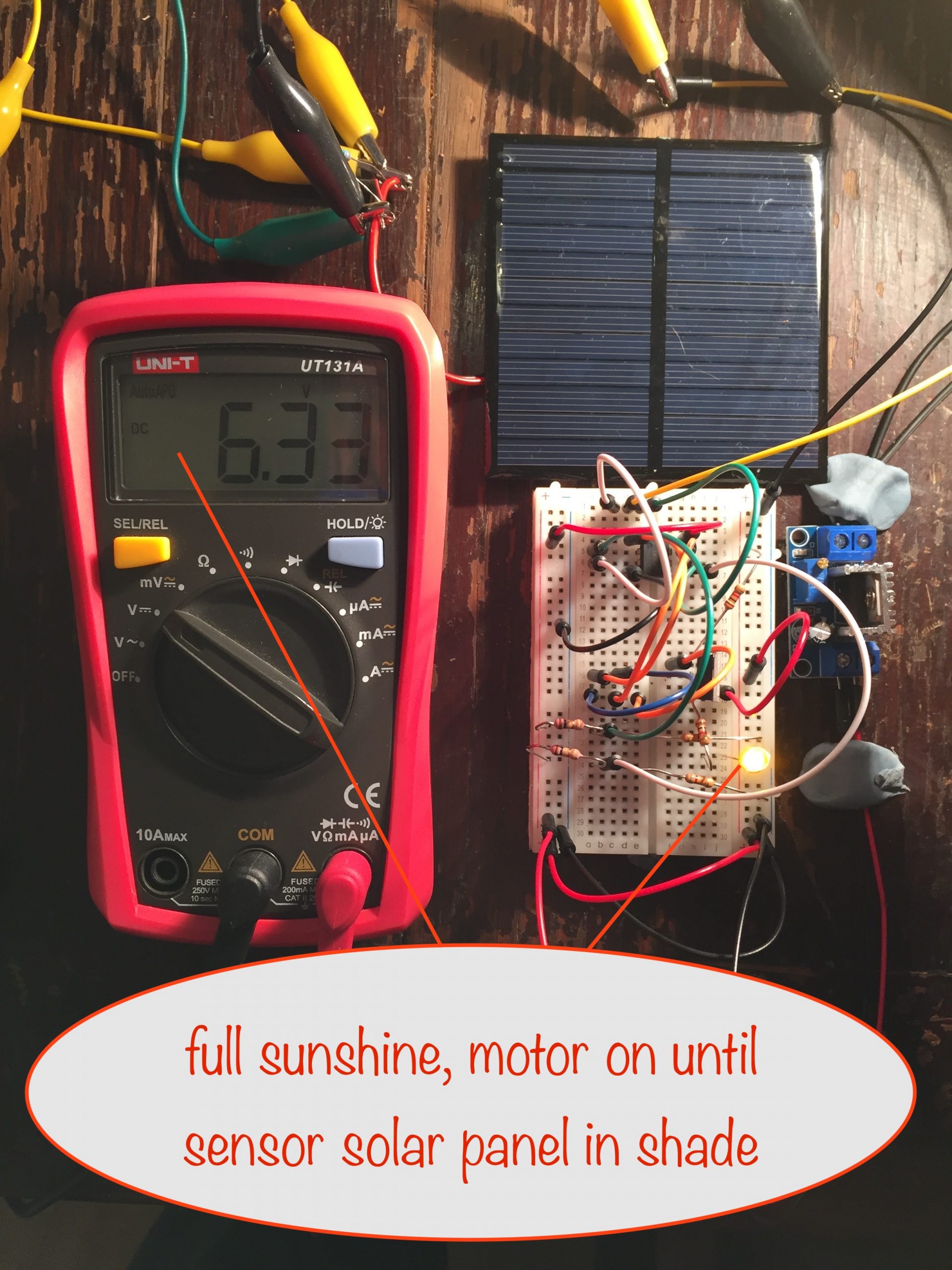
As you can see from the photos:

  • under full sunshine (above 5.4V) the motor is on
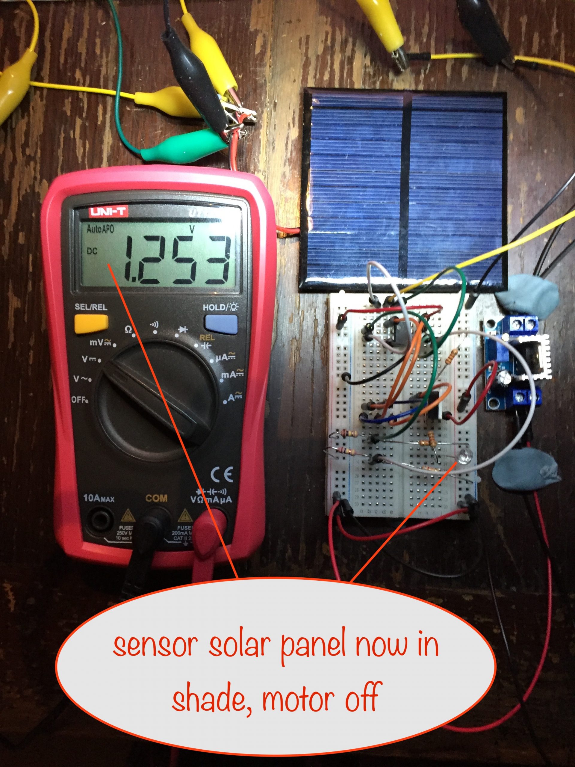
  • at 1.25V (ie above 1.1V and below 5.4V) the motor is off
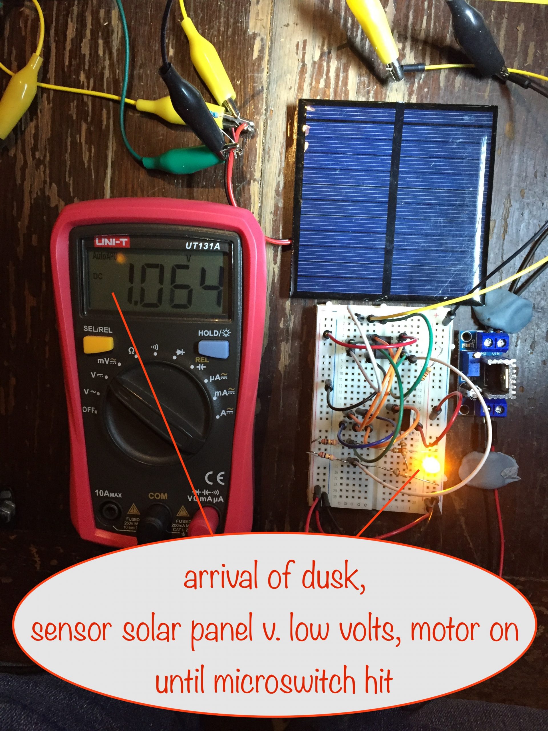
  • at 1.06V (ie below 1.1V) the motor is on

Perfect! 🤓

Now, about that challenge

At the start of this blog post I noted that there’s a challenge to overcome:

If the day is overcast and stays that way for a few hours, then when the sun does come out to play it’ll be sideways on to, or behind the sensor solar panel. That means no lifting and twisting can happen.

I have in mind the idea of placing another solar panel on the back of and wired in parallel with the sensor one but facing in the opposite direction.

I’m not sure how that’ll go:

  • in bright sunshine the overall voltage won’t reach as high because the one on the back will be at a lower voltage (less light reaching it) and so will tend to pull it down some
  • when in the shade, the voltage won’t reduce as much – because the additional one will be pointing in the other direction, and won’t be shaded from the sky
  • on overcast days it’ll probably increase the overall voltage, maybe causing some turning when it shouldn’t

Before I can decide if it’s the way to go, I’ve got some experimenting to do. I’ve got some low power 5V solar panels to hand so I’ll use them.

Scaled-up Solar Tracker – proof of concept part 2

see part 1 :: see part 3

Pole top mount design

I’ve completed the design of the mount for the pole top and have asked a local supplier to make the parts for me out of stainless steel.

As you can see from the sketches, the design of the pole top mount allows the solar panel frame to be pointed further up or down, depending on the time of year.

Continuing the build…

Here’s the starting point for part 2 of the build

photo showing the starting point for part 2 of the design and build
starting point for part 2 of the design and build

The parts I was waiting for arrived:

  • the stainless steel pole
  • the lifter bearing – the short length of bar with the recess for the ball bearings that the lifting eyelets attach to
  • the 1:810 reduction ratio gearbox

The installation went smoothly – I used grease to hold the ball bearings in place while putting the lifter bearing in place.

I’ve now realised there’s a slight issue there as regards portability. It’s because the only thing stopping the bearings falling out (apart from the grease) is the bottom of the pole resting on them. And if the pole is to be removed for easy portability, the grease will cause some of the bearings to stick to the bottom of the pole. Hmmm….

Ok, onwards…

I coupled the 100rpm N20 motor to the gearbox and gave it a test. All went well and it was satisfying to watch the steel pole go up and down, twisting back and forth as it did so. It did take 6 mins or so for one complete cycle but that’s needed to get the required torque.

The next step was to try it out, building up to a weight equivalent to the final build and see how well everything coped. So I filled a 6 pint milk container with water and attached it to the pole as the first step.

I switched on power and, as it took the strain, the gearbox started to grind and stutter and then locked solid. Oh dear…

I removed and stripped down the gearbox and found the reason – a few teeth on some of the gears had broken off.

photo showing stripped teeth and damaged gears in the speed reduction gearbox
damaged speed reduction gearbox

So it turns out that the speed reduction gearbox I chose simply can’t cope with the required torque – it couldn’t even cope with around a quarter of the required torque 🤪

I’ve spent a good few hours online trying to find an alternative. I’ve fired off a few emails to suppliers of those that look likely, so we’ll see.

A reminder of the mechanism’s core requirements

The motor has to be driven by a single lithium ion battery, down to 3.7v

RequirementReasoning
The motor has to be driven by a single 18650 lithium ion battery, down to 3.7vThe readily available TP4056 charging module can, with a small mod, detect darkness and then switch the motor on until everything is reset to the sunrise position
Absolute minimum of 2 120W solar panelsIdeally this would be 4 solar panels, giving an additional weight of 7.2kg, but 2 would do.
Torque needed at a minimum is around 3.5Nm (torque calculator)
The total weight of pole, frame, top pole mount and 2 solar panels is approximately 15kg, and the lifting force is applied at a distance of 45mm from the gearbox shaft.

If I can’t get a gearbox capable of handling the required torque, I’ll need to rethink a lot of the above. Fingers crossed! 😜

Scaled-up Solar Tracker – proof of concept

see part 2

an annotated photo showing the proof-of-concept design for a scaled-up solar tracker
scaled-up solar tracker version with major parts labelled

The previous final solar tracker was good for 3 x 10W solar panels (and could probably have managed a couple more).

I want to scale it up so it can cater for 400W of solar panels or better. The main hurdles to overcome:

  1. With increased surface area, the ability to withstand high winds
  2. The increased weight of 400W worth of the solar panels
  3. A method of mounting the solar panels on the lift-and-twist pole
  4. Making it portable so it can be used both at home and taken on camping holidays
  5. Mounting the finished build – allowing for temporary or fixed location

I think I’ve solved the first two by:

  • building a box made from 9mm plywood, using reinforced metal brackets to join the sides, top and bottom together
  • using a pulley system with 3mm nylon cord to do the heavy lifting, with a central reinforcer dowling to reduce the strain on the top of the box where the pulleys attach
  • using a gearbox with a 1:810 reduction ratio to get much more torque than given by the 1:90 used in the earlier version.
watch it in action

Differences between the proof-of-concept and the actual design

While waiting for parts to be delivered, I’ve progressed with various substitutes from the actual design.

I’ve used a length of wooden dowel inside the aluminium guiding tube. The design calls for a stainless steel tube with the bottom end closed off.

The mechanism that the lifting eyelets are attached to inside the aluminium guiding tube is currently a short piece of dowel. It’ll be replaced by a 12mm high stainless steel bar, with a 2mm deep recess in the top to take some 3mm ball bearings. The closed end of the stainless steel tube will rest on the ball bearings.

I was sent the wrong gearbox – it had a reduction ratio of 1:55 instead of the 1:506 ordered. I’m fighting a battle with the suppliers to get them to replace it, so in the meantime I’ve taken the opportunity to order one from a different supplier with a 1:810 reduction ratio – as I think it’ll better be able to do the heavy lifting.

Still to resolve

I still haven’t worked out how to attach the solar panels to the top of the stainless steel lift-and-twist tube.

On the one hand, they need to be detachable for portability, and on the other, they need to be able to be fixed firmly to the tube to resist high winds.

I’m not convinced that the 2mm wall thickness of the stainless steel tube is going to be strong enough.

Once it arrives I’ll be able to test it and see if it’s ok.

Lessons learned from this proof of concept

I’m stupid, hehe!

It wasn’t until I built it that I realized the 2 times mechanical advantage gain of the block-and-tackle was entirely pointless because it meant I had to have twice the diameter on the rotating plate than I’d otherwise need.

And having twice the diameter doubles the torque needed!

For the unitiated, torque is a measure of the rotational force-at-a-distance-from-the-centre – if you increase the distance, you increase the torque needed.

Without the block-and-tackle, I only need a diameter of 4cm for the rotating plate. So I can get rid of it, simplifying things while getting the torque I need.

Read more about solar trackers

Wikipedia does a good job in covering the concepts and advantages of solar trackers.

Speed-Sharer for promoting from the Zazzle ShowMe Forum

Newly released tool from the Nifty stable – promoting from the Zazzle Show Me Forum is now easier and quicker than ever.

annotated screenshot highlighting the major features
tool’s handy extras highlighted

Affiliate Benefits

  • Saves you time – the Nifty approach is quicker and easier
  • Makes it easy to get at the products / collections shared in the Show Me forum
  • Restrict to store lets you get only shares from your favourite store
  • Share to Twitter and Facebook and pin on Pinterest at the click of a button
  • As more designers find out about the tool, the more they’ll put into the ShowMe forum for us – and they’ll be organised by topic – nice!
  • Your referral id and tracking code are used as normal – if you’ve got a Nifty Promoter Program subscription, you’ll get clean links
  • Pinterest doesn’t like it when different people share the same image. Get round this by using image frames – then chances of that happening become very remote.

Find the new tool in the Nifty Promo Control Panel in Step 2 under Share individual products with Speed-Sharers

Designer Benefits

  • Now it’s so easy for Nifty-ers to share from the Show Me forum, it’s another way to get in front of real affiliates
  • More of your great designs / collections will be promoted when you post to an appropriate topic (aka thread) there
  • Posting to very specific topics will help you help affiliates even more
  • You can use the Speed Sharer as well
    • advance to a 50/50 referral split when you put in your referral id
    • stay on top of things by seeing what products / collections you’ve already shared by using the ‘Restrict to store’ feature

So what are you waiting for? Here’s a link to the Speed-Sharer for promoting from the Zazzle ShowMe Forum

Features

  • Twitter, Facebook and Pinterest buttons for easy sharing / pinning there
  • To help you see where your successes come from, your chosen tracking code automatically has the date appended and is prefixed by whatever button you click:
    • twt_ for Twitter
    • fbk_ for Facebook
    • pntrst_ for Pinterest
  • Topic Lister
  • Promote from a specific topic (message id)
  • Lots of help for each feature
  • Filtering by the date a topic was created:
    • today
    • since yesterday
    • last seven days
    • this month
    • since last month
    • all time
  • ‘Restrict to store’ lets you see only products / collections from the given store
  • Handy link to Zazzle’s community search page
  • Link given to the topic for the displayed product / collection
  • Image frames for Pinterest to help keep your pins unique

We’d love to hear what you think, so drop off a comment and let us know! Thanks 😎