In this post:
- Slower motor with more torque
- Motor driver circuit tweaks
- Solar charge controller for battery
- Block diagram
- Mounted in garden at last
- Next steps
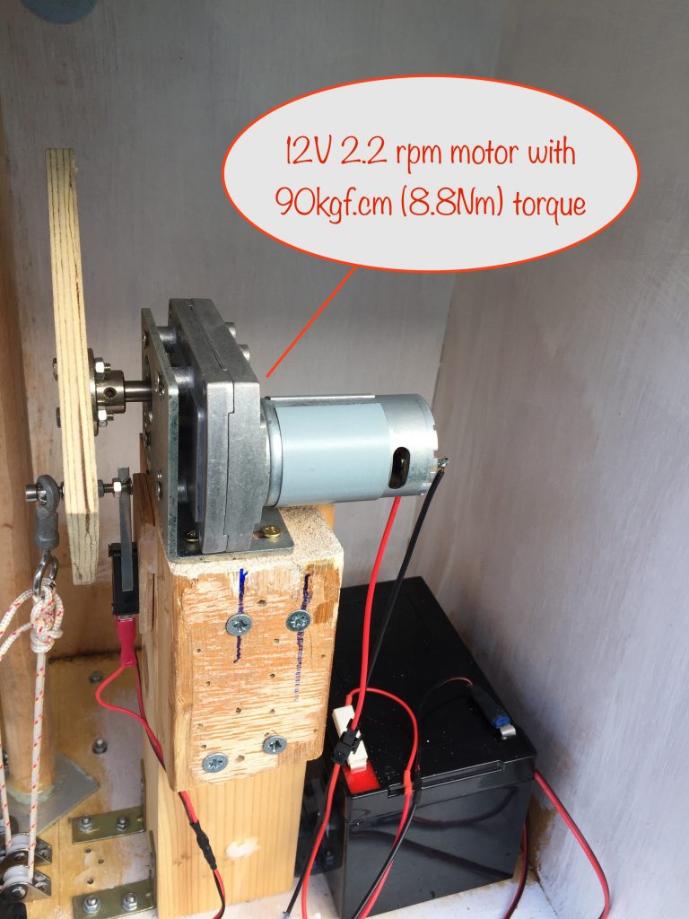
Slower motor with more torque
The new motor finally arrived. This one is 12V at 2.2rpm and has a torque of 90kgf.cm (8.8Nm). The torque is more than enough, so the step-up buck converter module I used to give the previous motor a torque boost isn’t needed anymore.
Motor driver circuit tweaks
One issue I had with the previous circuit was that I couldn’t measure the voltage set by the trimpot. Whenever I tried, it would cause the comparator output to switch on.
The values of the resistors in the voltage divider circuit were too high and meant that the slight change in impedance caused by connecting the voltmeter (and likely some rf noise being picked up by it as well) was enough to switch on the comparator when it shouldn’t.
I’ve now reduced the values proportionally and it’s no longer an issue. Here’s the tweaked circuit:
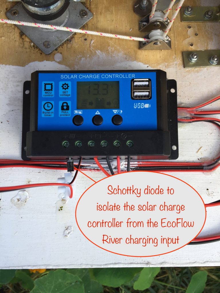
Solar charge controller
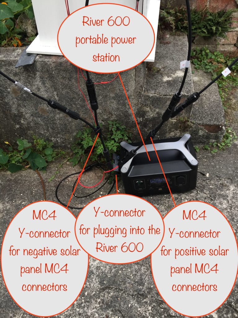
The motor driver circuit is powered by a 12V 12Ah AGM (absorbent glass mat) sealed lead acid battery. As it’s a deep discharge battery, a solar chage controller is needed to correctly charge it.
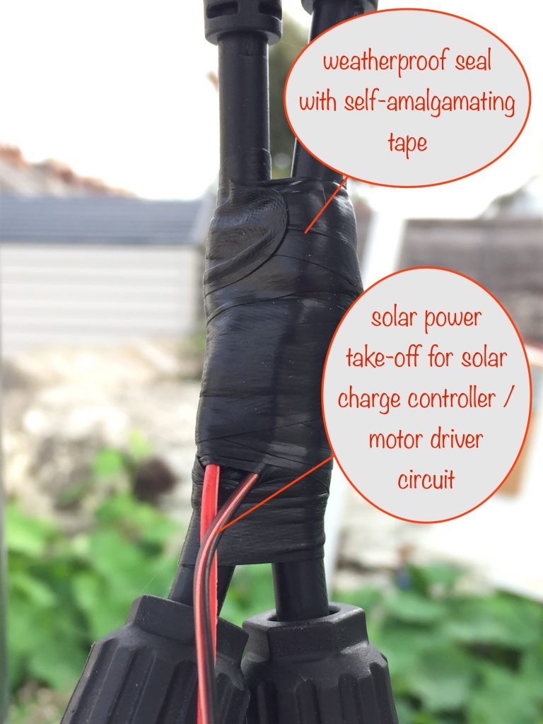
As it gets its power from the solar panels, I’ve put a diode in series with the input to the solar charge controller to isolate it from the solar panel input to the EcoFlow River 600, the main destination for the solar power.
To make the connection to the solar panels, I’ve tapped into the positive and negative MC4 cable branches – the ones that come from the output of the Y-connectors that connect the panels in parallel. I’ve used some self-amalgamating rubber tape to tightly cover the connection points and so make them weatherproof.
Block diagram
Here’s a diagram showing how the various blocks interconnect. Note that D2 (a 5 amp Schottky diode) prevents the solar charge controller and the EcoFlow River from interfering with each other:
Ground mounting the whole structure
Parts used:
- Stainless steel tube: 1m long, 28mm diameter, 2mm wall thickness – with an eyelet conveniently attached at one end
- Aluminium tube: 1.2m long, 35mm diameter, 2mm wall thickness
- M6 stainless steel bolt
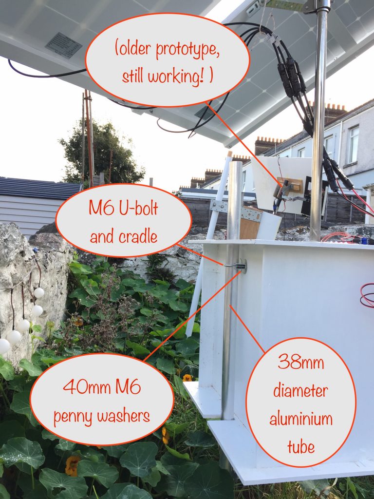
- 2 off M6 36mm extended leg u-bolts and cradles
- 4 off M6 40mm penny washers
- 90mm x 90mm x 50mm galvanized steel heavy duty bracket
Ground-mount pole assembly
I’d actually planned to set the stainless steel tube into a block of concrete and bury that but I got carried away and couldn’t wait to do it properly.
As it turns out, it looks like I might get away with just driving it into the ground as explained below. If not, I can always go back to the concrete block plan 😇
I drove the stainless steel tube, eyelet at the bottom, into the ground to a depth of around 40cm. I hadn’t planned on the eyelet, it just happened to be welded on when I bought it. Lucky really as the eyelet is preventing it from twisting and loosening.
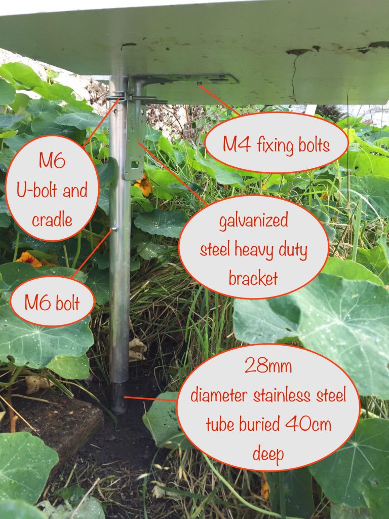
I hammered in some stones around the tube halfway down where it was buried to give additional support.
I’d already drilled holes in both tubes to take an M6 stainless steel bolt. That way I could hold the aluminium tube in place once it was slipped over the stainless steel one. I gave them an overlap of around 50cm.
Attaching the box to the ground-mount pole assembly
I used one of the u-bolts and cradles to attach the box directly to the aluminium pole. The fixing point was around 10cm from the top of the box.
I used the M6 40mm penny washers to make sure that the load was well spread and undue strain wasn’t placed on the 9mm thick plywood wall of the box.
To give support to the bottom of the box (as you can see in the photo above) I attached the heavy duty bracket to the aluminium pole with the other u-bolt and cradle and then used M4 bolts to attach the bracket to the bottom of the box.
It all seems to be robust enough and has survived a few days without showing any signs of failing. Yaay!
Next steps
Although it all seems to be working just fine, the motor is still a little too fast and continues to overshoot a little. Also, at dusk when it returns to facing the sunrise start position, it whips round rather quickly and could give a sharp blow to anyone standing too close.
The obvious solution is to use a speed controller so I’ve just ordered one from ebay. Hopefully it won’t affect the torque. We’ll see 🤞
I’ve also still to mount the solar charge controller inside the box and tidy up the wiring.